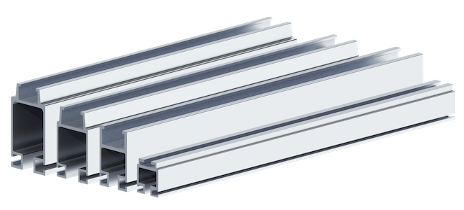
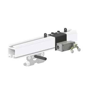
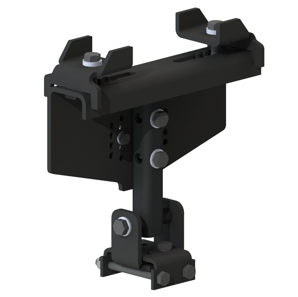
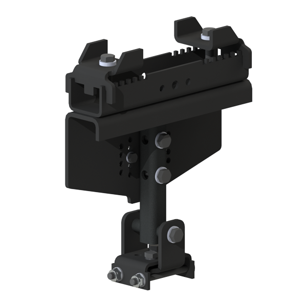
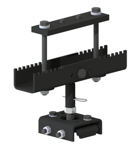
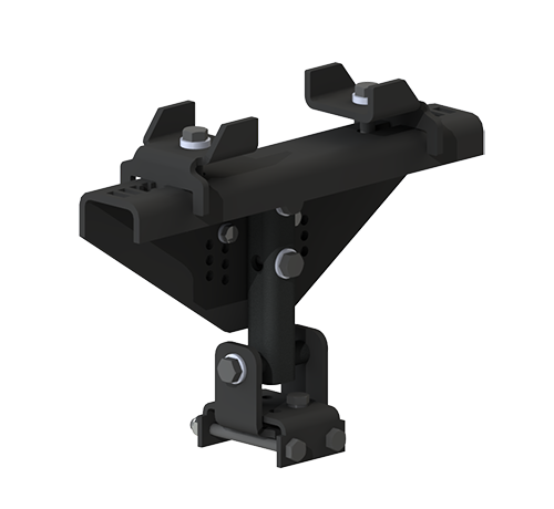
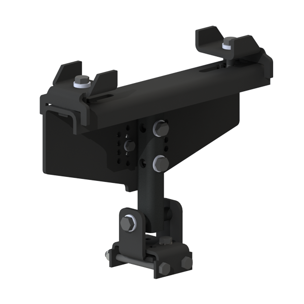
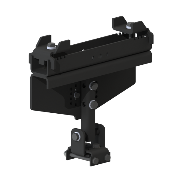
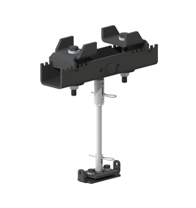
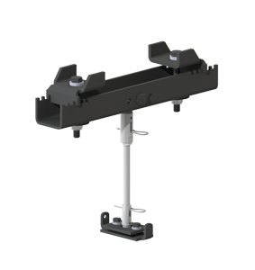
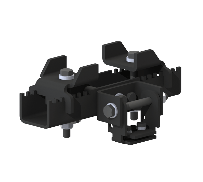
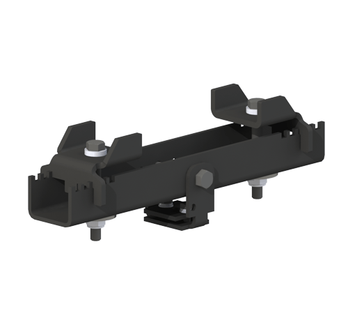
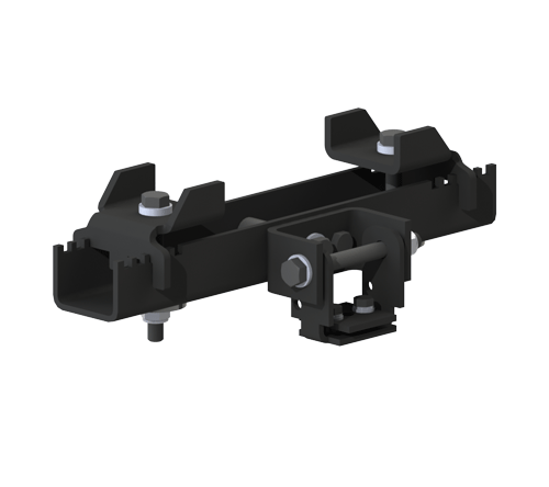
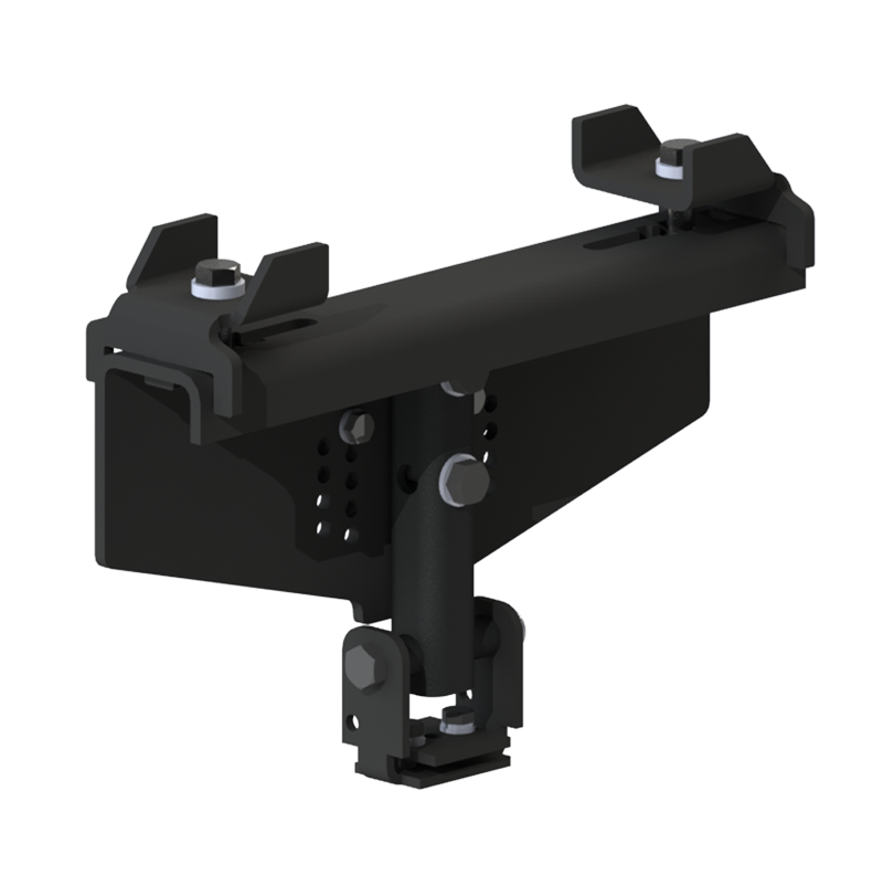
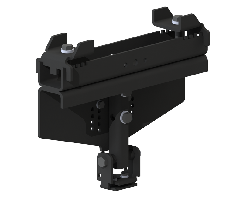
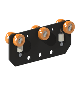
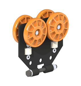
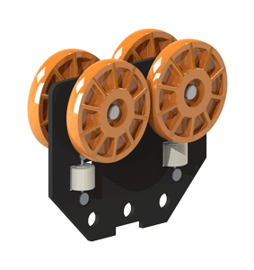
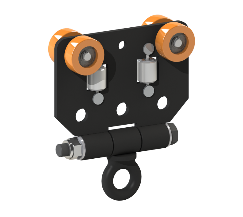
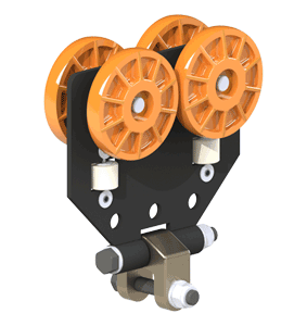
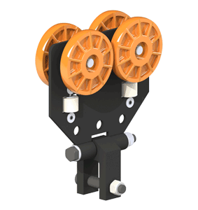
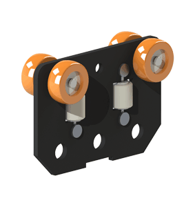
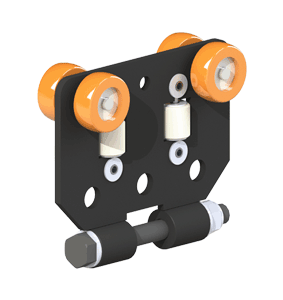
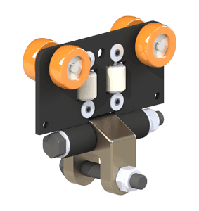
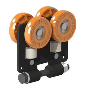
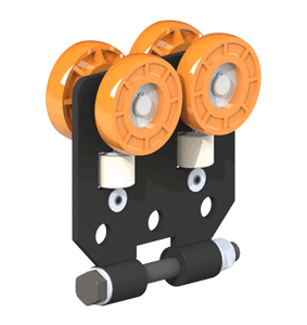
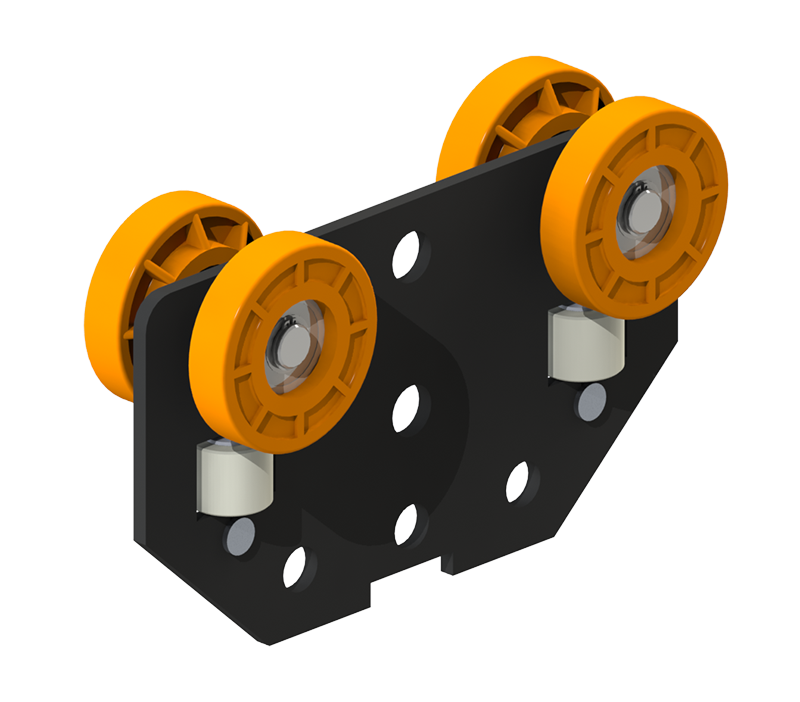
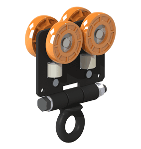
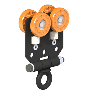
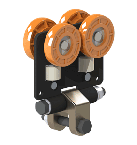
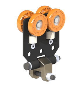
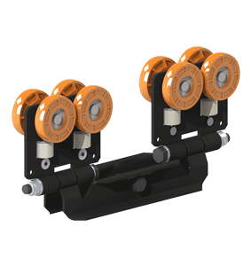
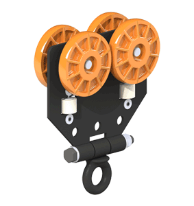
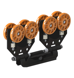
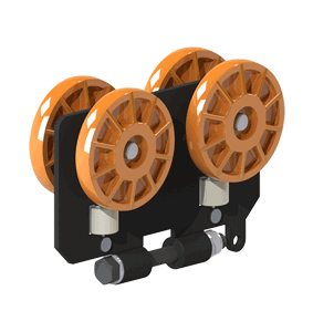
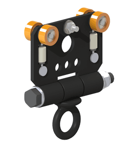
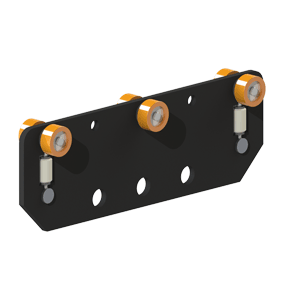
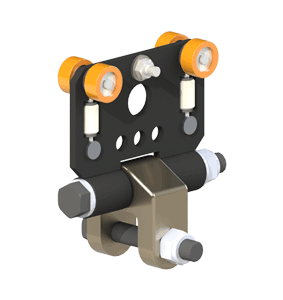
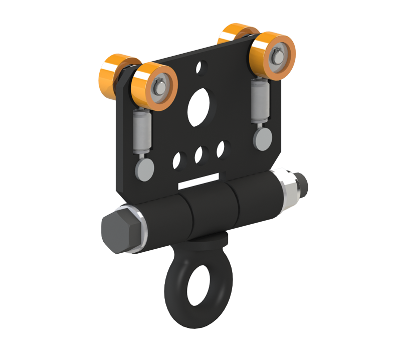
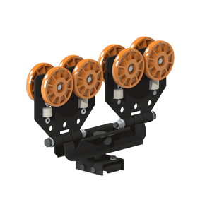
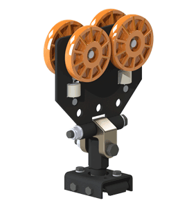
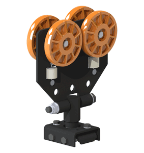
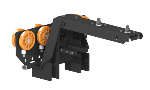
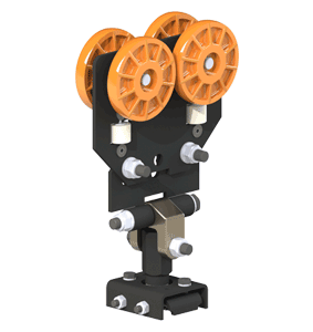
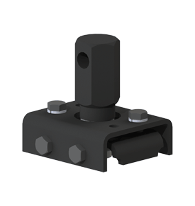
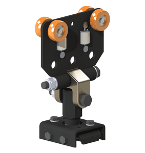
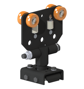
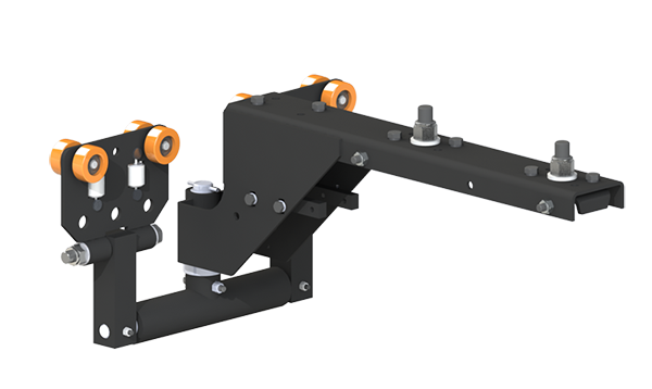
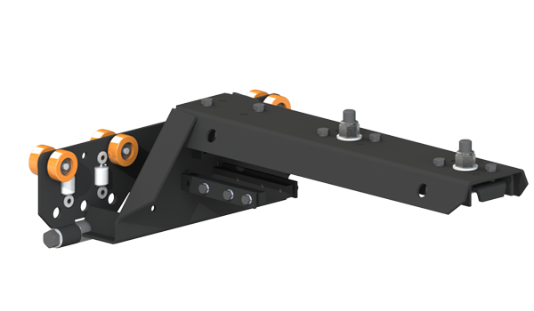
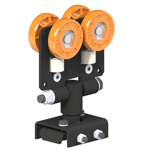
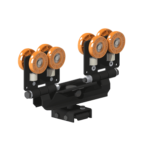
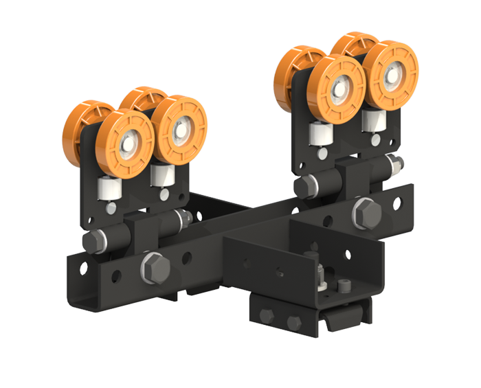
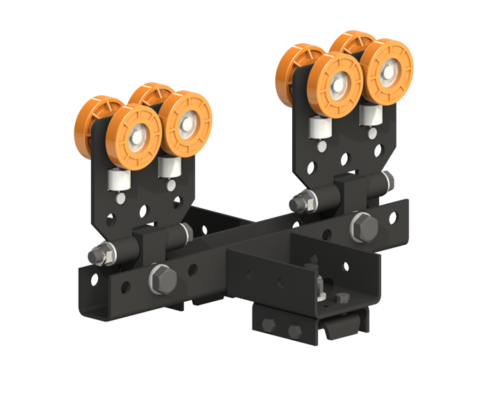
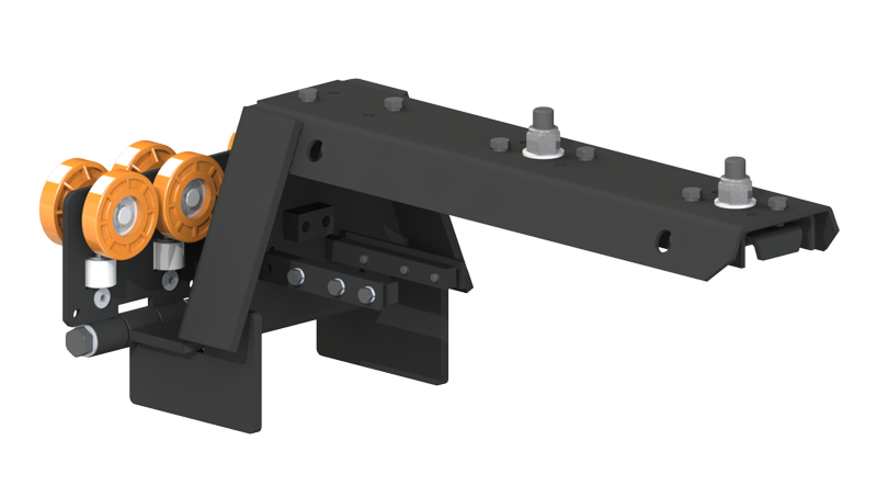
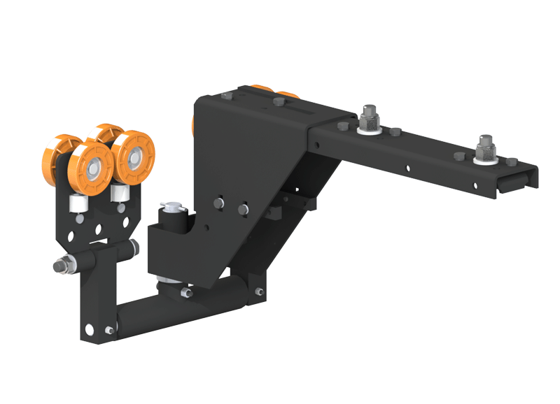
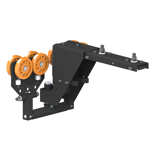
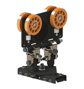
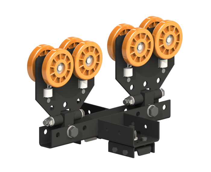
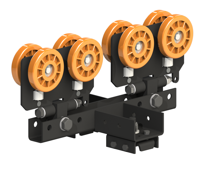
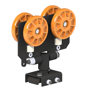
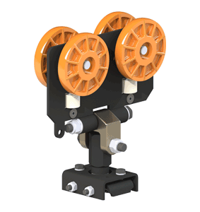
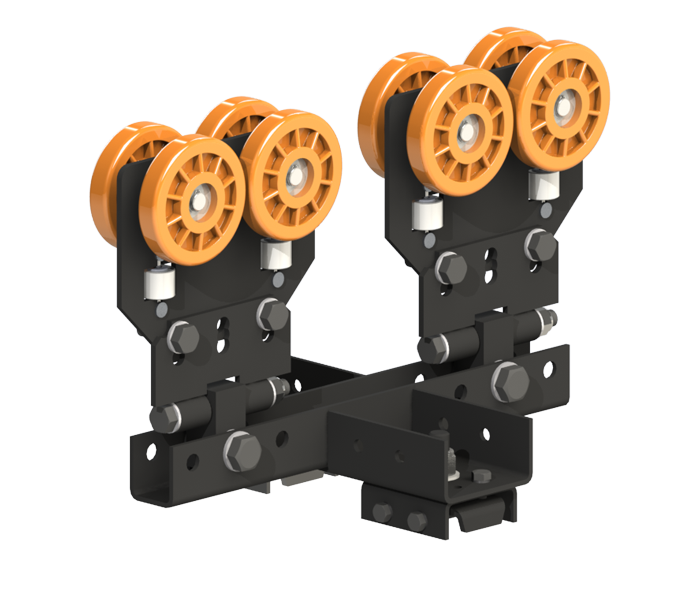
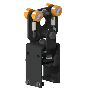
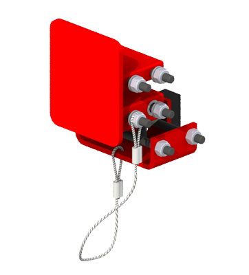
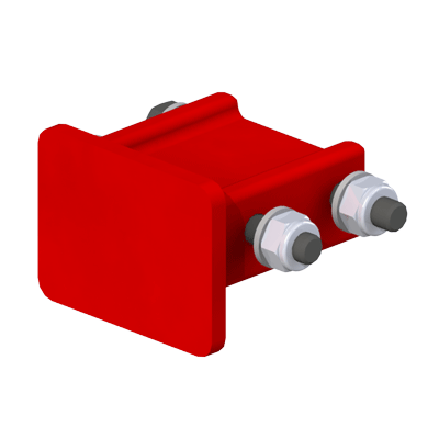
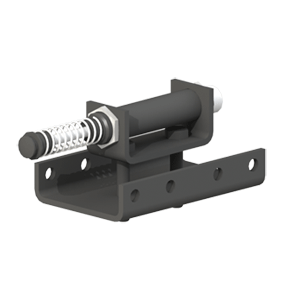
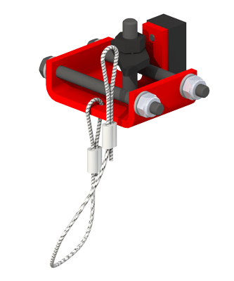
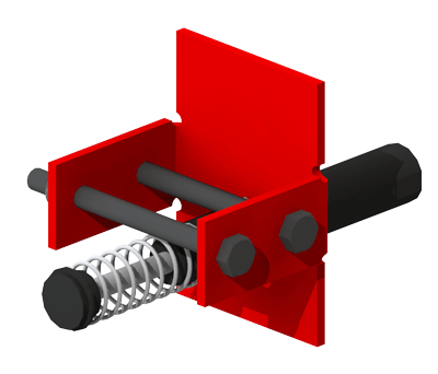
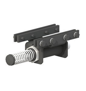
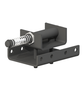
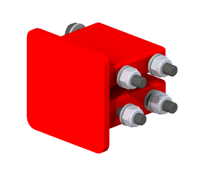
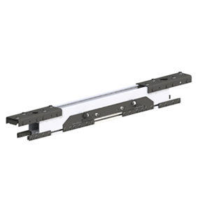
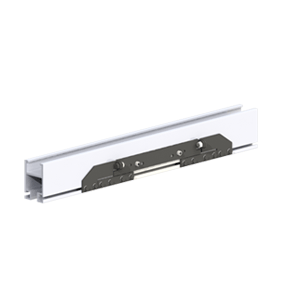
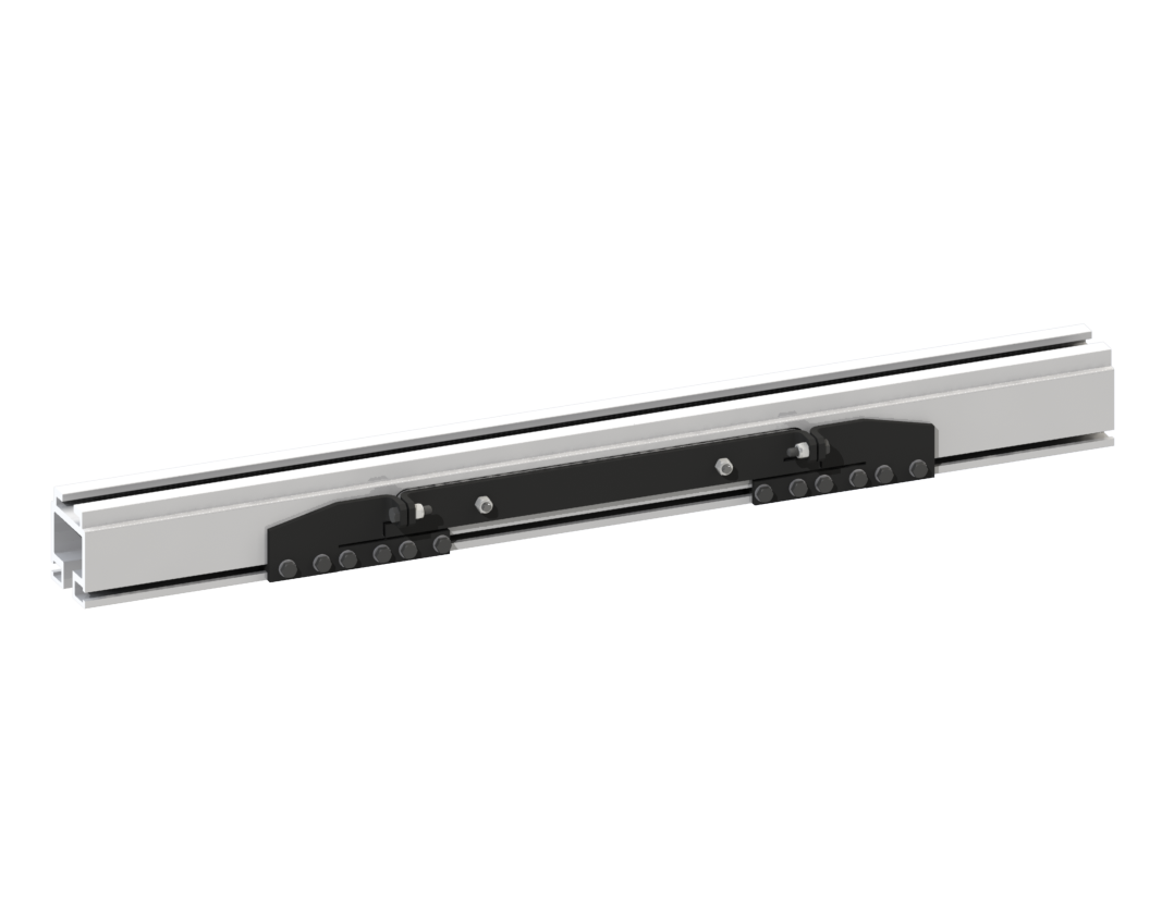
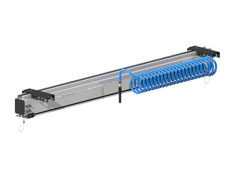
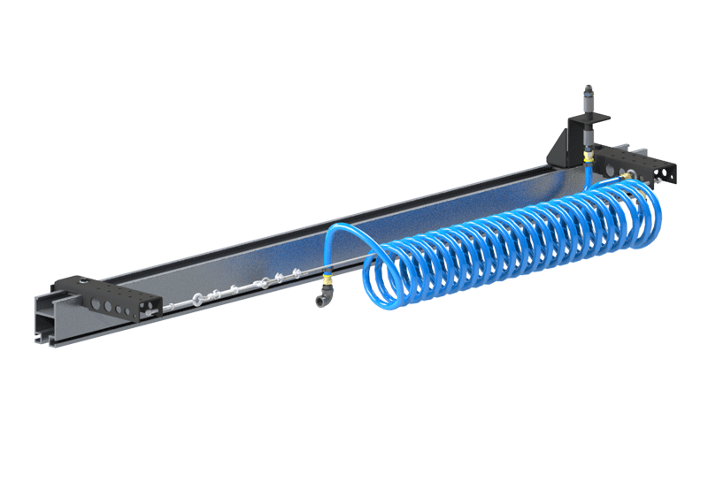
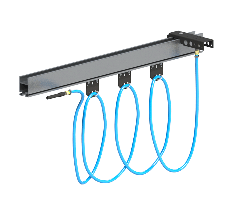
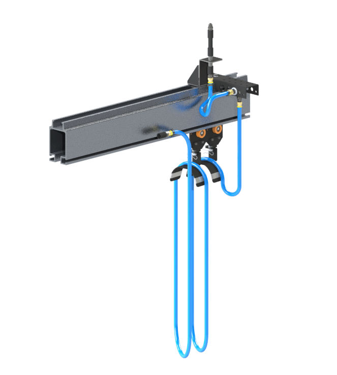
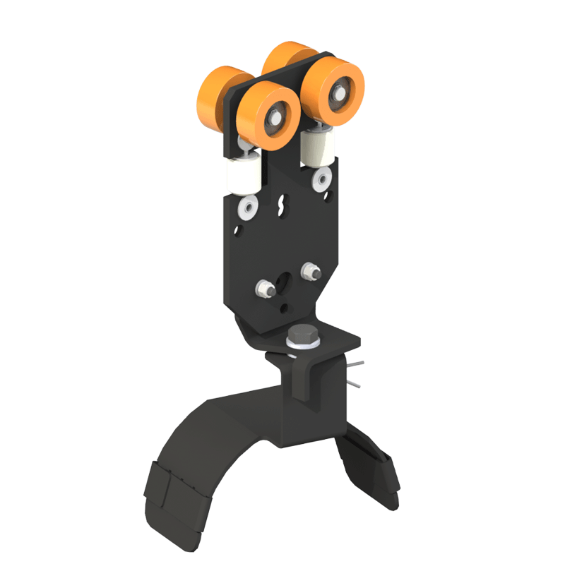
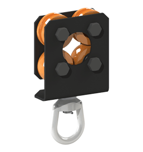
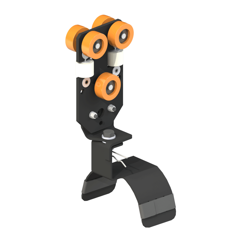
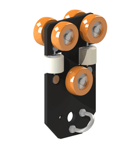
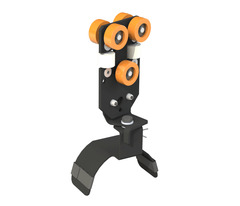
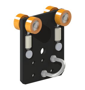
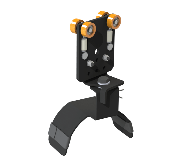
Enclosed Track Aluminum Rail Series
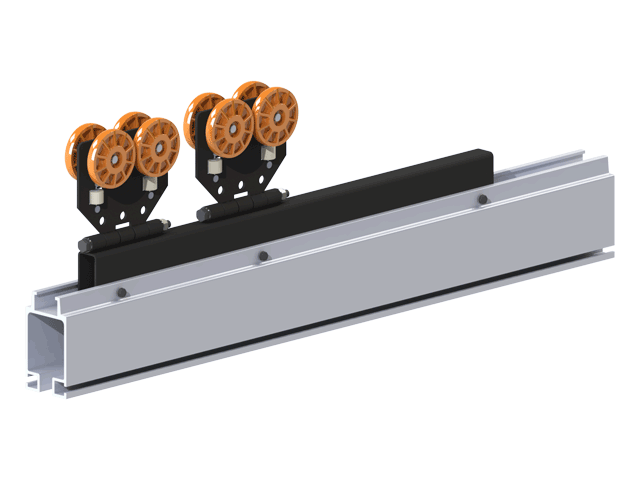
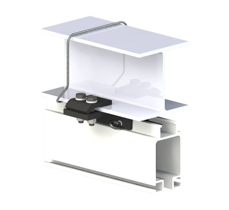
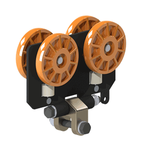
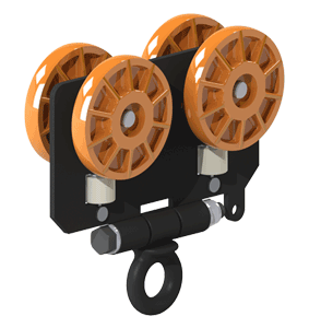
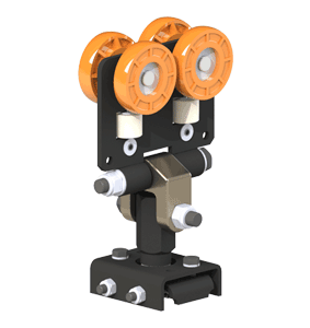
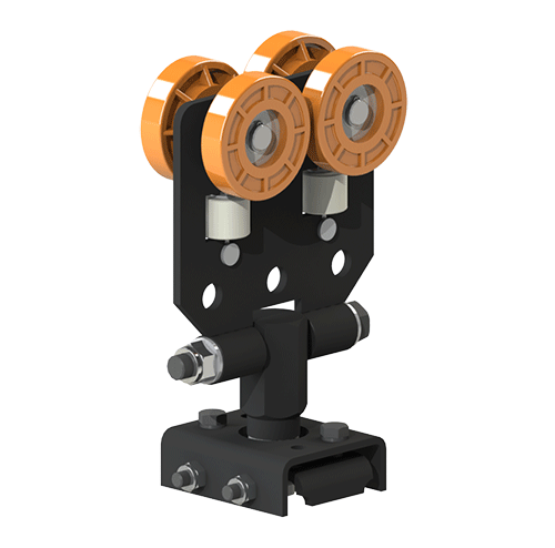
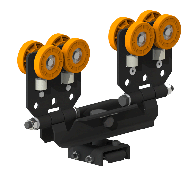
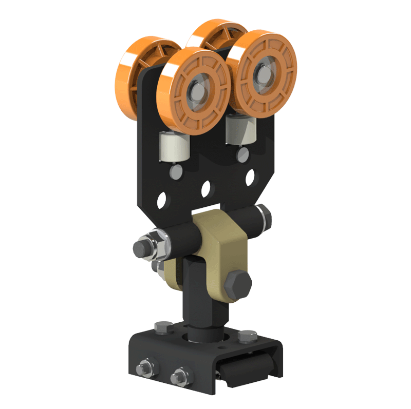
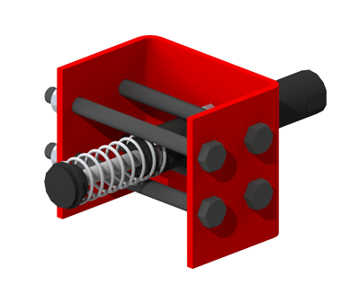
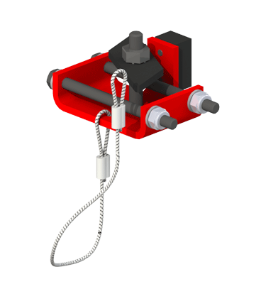
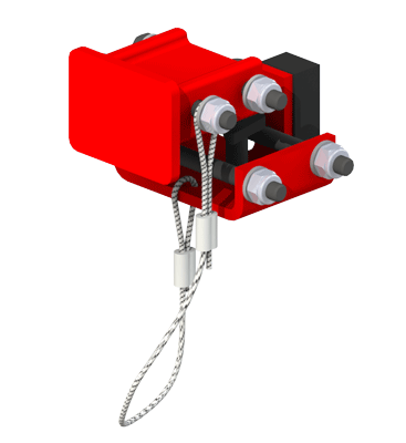
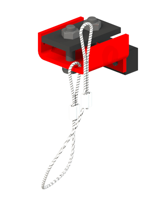
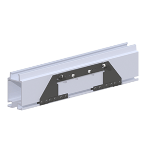
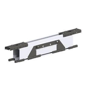
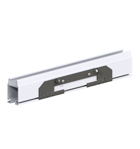
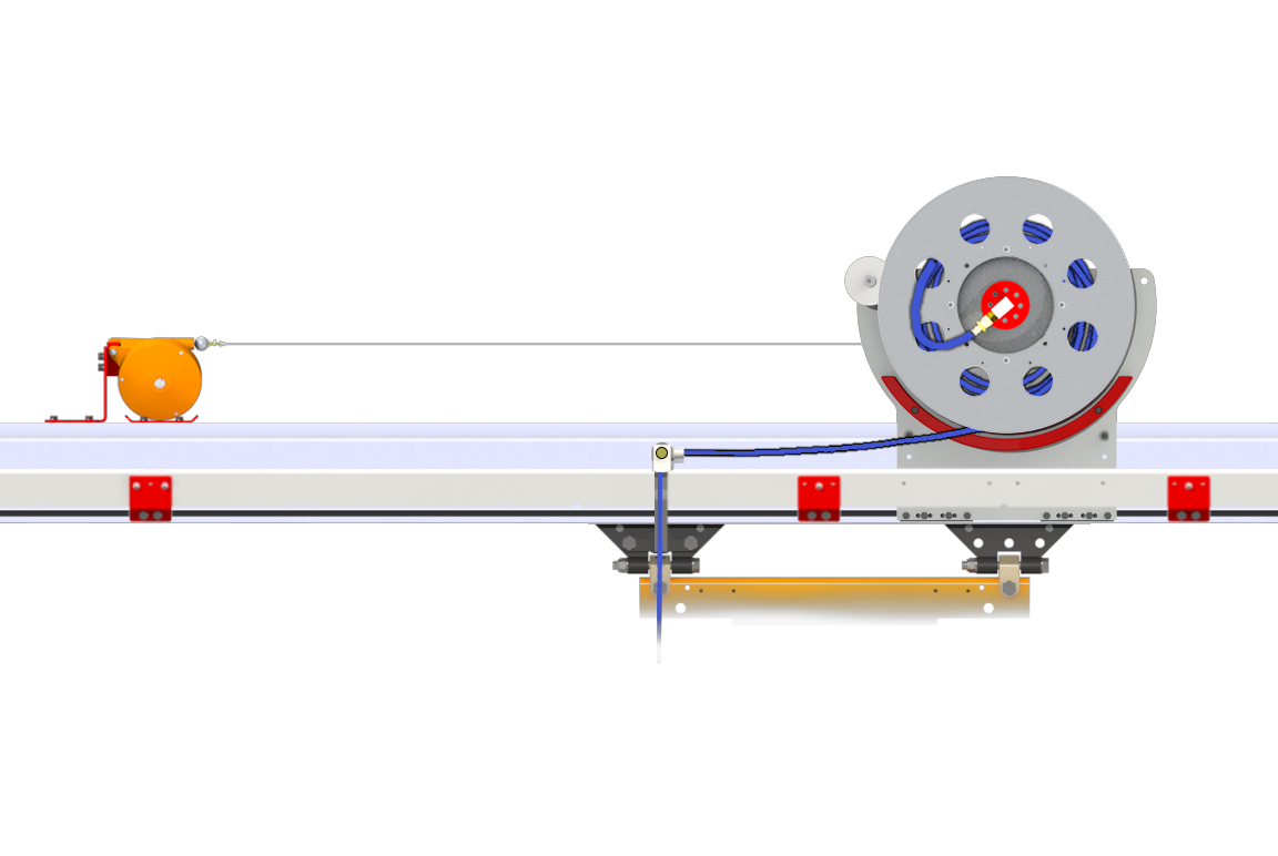
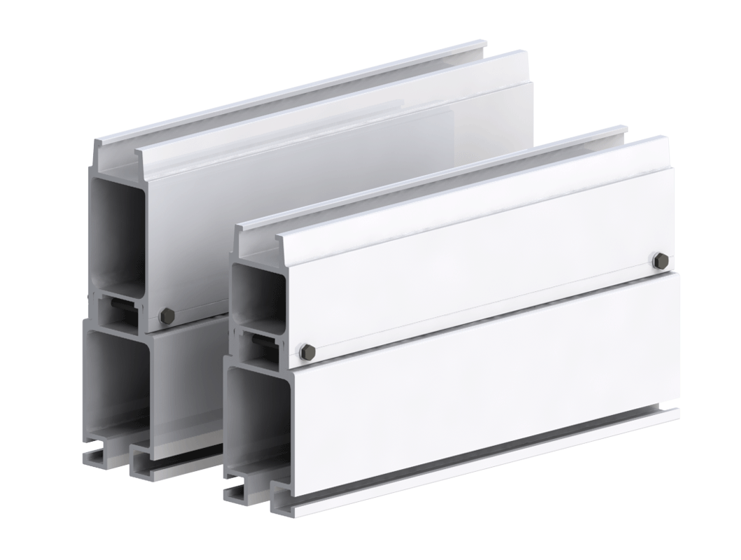
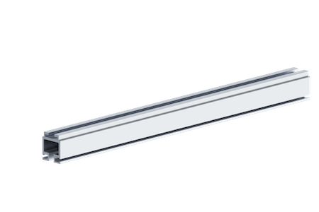
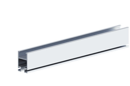
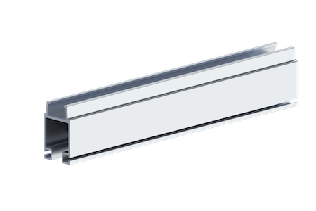
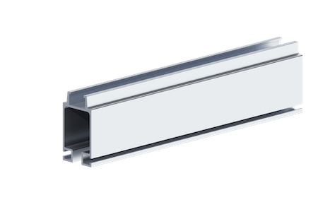
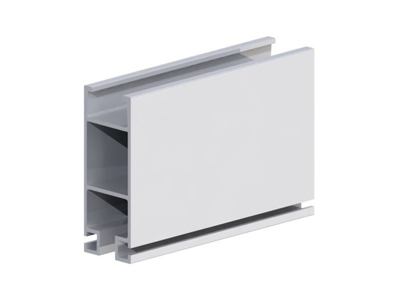
Knight’s RAD4110, RAD6110 and RAD7510 Aluminum Rail Series has an enclosed track design that is extruded from a lightweight, high-strength aluminum alloy. The lightweight aluminum rail eases installation and reduces overhead requirements. The enclosed Series Rail is the ideal solution, whether your load is located directly under the system or cantilevered off to the side. This series, combined with nylon trolley wheels, provides the lowest rolling resistance in the industry.
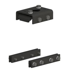
For capacities greater than 3000 lbs., a Backer rail can be integrated into Knight’s RAD7510 Rail. This allows for greater capacities to be achieved. Either 6″ (RAA4438) or 8″ (RAA4439) Backers are available. See chart below for specific capacities.
Knight also has implemented the RAD8110 Aluminum Rail Series to compete with European-style rails while offering a more robust profile. This rail style uses most accessories for the RAD4110 series. See charts below for specific capacities.
The TR2000 Series Aluminum Rail is a streamlined design ideal for applications under 550 lbs/ft. [249.5 kg/m] capacity. This innovative system allows for festooning trolleys and plant utilities to be attached to the main line rail system, allowing for more travel. Application types can include: light duty weld guns, work benches and stations, filter/regulator/lubrication (FRL), festooning, light fixtures, weld curtains, etc.
General Information
+Features
- Mechanical Properties: ASTM B221 6005-T5 Series Aluminum.
- Multiple Overhead and Floor Mounted Configurations.
- Supports Trolleys, End Trucks and Hangers.
- TR2000/RAD4110/RAD6110 Rail Lengths:
Up to 25 ft. [7.6m] without Splices. - RAD7510 Rail Lengths: Up to 30 ft. [9.1m] without Splices.
Benefits
- Transfer Loads in the “X” and “Y” Directions.
- Multiple Pre-Assembled Accessories.
- Accessories can be positioned along the rail, no welding required.
- Load Trolleys and End Trucks are designed for cantilevered and direct load applications.
- All Hangers and End Trucks are designed to prevent binding of bridges and runways.
Rail Series Specifications
+Enclosed Aluminum Rail Series
| Series | Max. Capacity | Product Weight |
|---|---|---|
| TR2000 | 550 lbs. [250kg] | 2.3 lbs/ ft. [3.33kg/m] |
| RAD4110 | 1,100 lbs. [499kg] | 4.3 lbs/ ft. [6.23kg/m] |
| RAD6110 | 1,600 lbs. [725kg] | 5.2 lbs/ ft. [7.7kg/m] |
| RAD7510 | 3000 lbs. [1,360kg] | 8.3 lbs/ ft. [12.02kg/m] |
| RAD8110 | 4000 lbs. [1814kg] | 6.4 lbs/ ft. [2.90kg/m] |
TR2000 Capacity Chart
+Rail Capacities
| Hanger Span | Deflection Criteria | ||||
|---|---|---|---|---|---|
| 1:350 Capacity* | 1:450 Capacity* | ||||
| ft | m | lbs | kg | lbs | kg |
| 5 | 1.52 | 550 | 250 | 470 | 213 |
| 6 | 1.83 | 400 | 181 | 340 | 154 |
| 7 | 2.13 | 350 | 159 | 295 | 134 |
| 8 | 2.45 | 250 | 113 | 210 | 95 |
| 9 | 2.74 | 200 | 90 | 170 | 77 |
| 10 | 3.05 | 175 | 80 | 150 | 68 |
| 11 | 3.35 | 160 | 72 | 135 | 61 |
| 12 | 3.66 | 135 | 61 | 115 | 52 |
| 13 | 3.96 | 125 | 57 | 105 | 47 |
| 14 | 4.27 | 115 | 52 | 95 | 43 |
| 15 | 4.57 | 90 | 40 | 75 | 34 |
| 16 | 4.88 | 75 | 34 | 65 | 30 |
| 17 | 5.18 | 65 | 30 | 55 | 25 |
*Due to Ergonomic considerations, each rail span distance is tested to determine the maximum single point load required to achieve a predetermined deflection based on a ratio of 1:350 (1” of deflection for each 350” of length) or 1:450 (1” of deflection in 450” of length).
For purposes of estimating approximate ergonomic force requirements, the following
formula may be used:
Fs = frictional force = 0.009 x total mass. This indicates the maximum effort (in lbf) required to overcome inertia. Effort required to sustain movement, Fk (dynamic friction force) is generally 0.35 times the frictional force.
E.g.;
Fs = 0.009 x 250 lbs. (113.4 kg) mass = 2.25 lbf (0.9 kg) required to overcome inertia.
Fk = 0.009 x 250 lbs. (113.4 kg) mass x .35 = .79 lbf (0.36 kg) required to sustain movement.
Cantilevered Capacities (based on 8ft. hanger span)
| Cantilevered | Deflection Criteria | ||||
|---|---|---|---|---|---|
| 1:350 Capacity* | 1:450 Capacity* | ||||
| ft | m | lbs | kg | lbs | kg |
| 1 | .30 | 100 | 45 | 75 | 34 |
| 2 | .61 | 50 | 23 | 35 | 16 |
Elastic deformation: This type of deformation is reversible. Once the forces are removed, the object returns to its original shape. The elastic range ends when the material reaches its yield strength. At this point deformation begins.
Plastic deformation: This type of deformation is not reversible. Once an object reaches this point, it will not return to its original shape. Plastic deformation ends with the fracture of the material.
Knight Global follows material handling industry standards in determining the capacity ratings for enclosed track overhead workstation crane systems. Each component (e.g. rail, hangers, trolleys, etc.) is individually tested to establish its ultimate failure point. From this number, a safe working load is then assigned to the component. Each rail span length is then tested to determine the maximum single point load required to achieve a predetermined deflection based on a 1:350 ratio (1″ of deflection for each 350″ of length). The recommended rated capacity chart is based upon single point loading for the listed spans.
RAD4110 Capacity Chart
+Rail Capacities
| Hanger Span | Deflection Criteria | ||||
|---|---|---|---|---|---|
| 1:350 Capacity* | 1:450 Capacity* | ||||
| ft | m | lbs | kg | lbs | kg |
| 5 | 1.52 | 1100 | 499 | 950 | 431 |
| 6 | 1.83 | 1100 | 499 | 950 | 431 |
| 7 | 2.13 | 1050 | 476 | 875 | 397 |
| 8 | 2.45 | 1050 | 476 | 775 | 351 |
| 9 | 2.74 | 950 | 431 | 675 | 306 |
| 10 | 3.05 | 850 | 385 | 650 | 295 |
| 11 | 3.35 | 700 | 317 | 550 | 250 |
| 12 | 3.66 | 550 | 250 | 450 | 204 |
| 13 | 3.96 | 500 | 226 | 385 | 175 |
| 14 | 4.27 | 435 | 197 | 300 | 136 |
| 15 | 4.57 | 350 | 159 | 250 | 113 |
| 16 | 4.88 | 335 | 152 | 250 | 113 |
| 17 | 5.18 | 280 | 127 | 175 | 79 |
| 18 | 5.48 | 265 | 120 | 175 | 79 |
| 19 | 5.79 | 230 | 104 | 150 | 68 |
| 20 | 6.10 | 210 | 95 | 150 | 68 |
| 21 | 6.40 | 195 | 88 | 125 | 57 |
| 22 | 6.70 | 175 | 79 | 125 | 57 |
| 23 | 7.01 | 160 | 73 | 125 | 57 |
| 24 | 7.31 | 145 | 66 | 100 | 57 |
*Due to Ergonomic considerations, each rail span distance is tested to determine the maximum single point load required to achieve a predetermined deflection based on a ratio of 1:350 (1” of deflection for each 350” of length) or 1:450 (1” of deflection in 450” of length)
For purposes of estimating approximate ergonomic force requirements, the following
formula may be used:
Fs = frictional force = 0.009 x total mass. This indicates the maximum effort (in lbf) required to overcome inertia. Effort required to sustain movement, Fk (dynamic friction force) is generally 0.35 times the frictional force.
E.g.;
Fs = 0.009 x 250 lbs. (113.4 kg) mass = 2.25 lbf (0.9 kg) required to overcome inertia.
Fk = 0.009 x 250 lbs. (113.4 kg) mass x .35 = .79 lbf (0.36 kg) required to sustain movement.
Cantilevered Capacities (based on an optimum 8ft. hanger span)
| Cantilevered | Deflection Criteria | ||||||
|---|---|---|---|---|---|---|---|
| 1:350 Capacity* | 1:450 Capacity* | ||||||
| ft | m | lbs | kg | lbs | kg | ||
| 1 | .30 | 900 | 408 | 750 | 340 | ||
| 2 | .61 | 325 | 147 | 300 | 136 | ||
| 3 | .91 | 125 | 57 | 100 | 45 | ||
| 4 | 1.20 | 35 | 16 | 30 | 14 | ||
Elastic deformation: This type of deformation is reversible. Once the forces are removed, the object returns to its original shape. The elastic range ends when the material reaches its yield strength. At this point deformation begins.
Plastic deformation: This type of deformation is not reversible. Once an object reaches this point, it will not return to its original shape. Plastic deformation ends with the fracture of the material.
Knight Global follows material handling industry standards in determining the capacity ratings for enclosed track overhead workstation crane systems. Each component (e.g. rail, hangers, trolleys,etc.) is individually tested to establish its ultimate failure point. From this number, a safe working load is then assigned to the component. Each rail span length is then tested to determine the maximum single point load required to achieve a predetermined deflection based on a 1:350 ratio (1″ of deflection for each 350″ of length). The recommended rated capacity chart is based upon single point loading for the listed spans.
RAD6110 Capacity Chart
+Rail Capacities
| Hanger Span | Deflection Criteria | ||||
|---|---|---|---|---|---|
| 1:350 Capacity* | 1:450 Capacity* | ||||
| ft | m | lbs | kg | lbs | kg |
| 5 | 1.52 | 1600 | 725 | 1300 | 590 |
| 6 | 1.83 | 1600 | 725 | 1300 | 590 |
| 7 | 2.13 | 1500 | 680 | 1175 | 533 |
| 8 | 2.45 | 1475 | 699 | 1075 | 488 |
| 9 | 2.74 | 1400 | 635 | 1025 | 465 |
| 10 | 3.05 | 1325 | 601 | 925 | 453 |
| 11 | 3.35 | 1100 | 499 | 875 | 397 |
| 12 | 3.66 | 950 | 431 | 750 | 340 |
| 13 | 3.96 | 825 | 374 | 650 | 295 |
| 14 | 4.27 | 750 | 340 | 575 | 261 |
| 15 | 4.57 | 675 | 306 | 515 | 233 |
| 16 | 4.88 | 600 | 272 | 470 | 213 |
| 17 | 5.18 | 525 | 238 | 405 | 184 |
| 18 | 5.48 | 450 | 204 | 350 | 159 |
| 19 | 5.79 | 425 | 193 | 325 | 147 |
| 20 | 6.10 | 400 | 181 | 300 | 136 |
| 21 | 6.40 | 360 | 163 | 275 | 125 |
| 22 | 6.70 | 320 | 145 | 250 | 113 |
| 23 | 7.01 | 285 | 129 | 210 | 95 |
| 24 | 7.31 | 245 | 111 | 185 | 84 |
*Due to Ergonomic considerations, each rail span distance is tested to determine the maximum single point load required to achieve a predetermined deflection based on a ratio of 1:350 (1” of deflection for each 350” of length) or 1:450 (1” of deflection in 450” of length).
For purposes of estimating approximate ergonomic force requirements, the following
formula may be used:
Fs = frictional force = 0.009 x total mass. This indicates the maximum effort (in lbf) required to overcome inertia. Effort required to sustain movement, Fk (dynamic friction force) is generally 0.35 times the frictional force.
E.g.;
Fs = 0.009 x 250 lbs. (113.4 kg) mass = 2.25 lbf (0.9 kg) required to overcome inertia.
Fk = 0.009 x 250 lbs. (113.4 kg) mass x .35 = .79 lbf (0.36 kg) required to sustain movement.
Cantilevered Capacities (based on an optimum 8ft. hanger span)
| Cantilevered | Deflection Criteria | ||||||
|---|---|---|---|---|---|---|---|
| 1:350 Capacity* | 1:450 Capacity* | ||||||
| ft | m | lbs | kg | lbs | kg | ||
| 1 | .30 | 2200 | 998 | 1700 | 771 | ||
| 2 | .61 | 1000 | 454 | 775 | 351 | ||
| 3 | .91 | 600 | 272 | 475 | 215 | ||
| 4 | 1.20 | 250 | 113 | 125 | 57 | ||
RAD7510 Capacity Chart
+Rail Capacities
| Hanger Span | Deflection Criteria | ||||||||||||
|---|---|---|---|---|---|---|---|---|---|---|---|---|---|
| RAD7510 Series | RAD7510 + 6″ Backer | RAD7510 + 8″ Backer | |||||||||||
| 1:350 Capacity* | 1:450 Capacity* | 1:350 Capacity* | 1:450 Capacity* | 1:350 Capacity* | 1:450 Capacity* | ||||||||
| ft | m | lbs | kg | lbs | kg | lbs | kg | lbs | kg | lbs | kg | lbs | kg |
| 5 | 1.52 | 3000 | 1360 | 2700 | 1225 | 12170 | 5520 | 12170 | 5520 | 16355 | 7418 | 16355 | 7418 |
| 6 | 1.83 | 3000 | 1360 | 2700 | 1225 | 10130 | 4595 | 10130 | 4595 | 13620 | 6178 | 13620 | 6178 |
| 7 | 2.13 | 3000 | 1360 | 2700 | 1225 | 8670 | 3933 | 8670 | 3933 | 11660 | 5289 | 11660 | 5289 |
| 8 | 2.45 | 3000 | 1360 | 2700 | 1225 | 7575 | 3436 | 7575 | 3436 | 10190 | 4622 | 10190 | 4622 |
| 9 | 2.74 | 2700 | 1225 | 2400 | 1088 | 6720 | 3048 | 6720 | 3048 | 9045 | 4103 | 9045 | 4103 |
| 10 | 3.05 | 2500 | 1134 | 2000 | 907 | 6035 | 2737 | 6035 | 2737 | 8130 | 3688 | 8130 | 3688 |
| 11 | 3.35 | 2500 | 1134 | 1900 | 862 | 5475 | 2483 | 5475 | 2483 | 7375 | 3345 | 7375 | 3345 |
| 12 | 3.66 | 2500 | 1134 | 1800 | 816 | 5010 | 2272 | 5010 | 2272 | 6750 | 3062 | 6750 | 3062 |
| 13 | 3.96 | 2000 | 907 | 1800 | 816 | 4610 | 2091 | 4610 | 2091 | 6215 | 2819 | 6215 | 2819 |
| 14 | 4.27 | 2000 | 907 | 1500 | 680 | 4270 | 1937 | 4270 | 1937 | 5760 | 2613 | 5760 | 2613 |
| 15 | 4.57 | 1900 | 861 | 1500 | 680 | 3975 | 1803 | 3975 | 1803 | 5365 | 2434 | 5365 | 2434 |
| 16 | 4.88 | 1800 | 816 | 1200 | 544 | 3710 | 1683 | 3710 | 1683 | 5015 | 2275 | 5015 | 2275 |
| 17 | 5.18 | 1700 | 771 | 1200 | 544 | 3480 | 1578 | 3480 | 1578 | 4750 | 2134 | 4750 | 2134 |
| 18 | 5.48 | 1600 | 726 | 1000 | 453 | 3275 | 1486 | 3275 | 1486 | 4430 | 2009 | 4430 | 2009 |
| 19 | 5.79 | 1450 | 658 | 1000 | 453 | 3090 | 1402 | 3090 | 1402 | 4185 | 1898 | 4185 | 1898 |
| 20 | 6.10 | 1300 | 590 | 900 | 408 | 2925 | 1327 | 2925 | 1327 | 3965 | 1798 | 3965 | 1798 |
| 21 | 6.40 | 1100 | 499 | 900 | 408 | 2775 | 1259 | 2535 | 1550 | 3760 | 1705 | 3760 | 1705 |
| 22 | 6.70 | 900 | 408 | 800 | 363 | 2635 | 1195 | 2285 | 1036 | 3575 | 1622 | 3560 | 1615 |
| 23 | 7.01 | 900 | 408 | 700 | 317 | 2510 | 1139 | 2070 | 939 | 3410 | 1547 | 3230 | 1465 |
| 24 | 7.31 | 885 | 402 | 700 | 317 | 2390 | 1084 | 1880 | 853 | 3255 | 1476 | 2945 | 1336 |
| 25 | 7.62 | 850 | 386 | 700 | 317 | 2250 | 1021 | 1710 | 776 | 3110 | 1411 | 2690 | 1220 |
| 26 | 7.92 | 725 | 329 | 700 | 317 | 2060 | 934 | 1555 | 705 | 2980 | 1352 | 2465 | 1118 |
| 27 | 8.23 | 725 | 329 | 675 | 306 | 1890 | 857 | 1420 | 644 | 2855 | 1295 | 2260 | 1025 |
| 28 | 8.53 | 600 | 272 | 550 | 250 | 1735 | 787 | 1300 | 590 | 2735 | 1241 | 2075 | 941 |
| 29 | 8.83 | 600 | 272 | 550 | 250 | 1595 | 723 | 1190 | 540 | 2525 | 1145 | 1910 | 866 |
*Due to Ergonomic considerations, each rail span distance is tested to determine the maximum single point load required to achieve a predetermined deflection based on a ratio of 1:350 (1” of deflection for each 350” of length) or 1:450 (1” of deflection in 450” of length).
For purposes of estimating approximate ergonomic force requirements, the following
formula may be used:
Fs = frictional force = 0.009 x total mass. This indicates the maximum effort (in lbf) required to overcome inertia. Effort required to sustain movement, Fk (dynamic friction force) is generally 0.35 times the frictional force.
E.g.;
Fs = 0.009 x 250 lbs. (113.4 kg) mass = 2.25 lbf (0.9 kg) required to overcome inertia.
Fk = 0.009 x 250 lbs. (113.4 kg) mass x .35 = .79 lbf (0.36 kg) required to sustain movement.
Cantilevered Capacities (based on an optimum 8ft. hanger span)
| Cantilevered | Deflection Criteria | ||||||
|---|---|---|---|---|---|---|---|
| 1:350 Capacity* | 1:450 Capacity* | ||||||
| ft | m | lbs | kg | lbs | kg | ||
| 1 | .30 | 3000 | 1361 | 2700 | 1225 | ||
| 2 | .61 | 2200 | 998 | 2000 | 907 | ||
| 3 | .91 | 900 | 408 | 775 | 352 | ||
| 4 | 1.20 | 375 | 170 | 325 | 147 | ||
RAD8110 Capacity Chart
+Rail Capacities
| Hanger Span | Deflection Criteria | ||||
|---|---|---|---|---|---|
| 1:350 Capacity* | 1:450 Capacity* | ||||
| ft | m | lbs | kg | lbs | kg |
| 5 | 1.52 | 4000 | 1814 | 4000 | 1814 |
| 6 | 1.83 | 3575 | 1622 | 3575 | 1622 |
| 7 | 2.13 | 3060 | 1388 | 3060 | 1388 |
| 8 | 2.45 | 2670 | 1211 | 2670 | 1211 |
| 9 | 2.74 | 2370 | 1075 | 2370 | 1075 |
| 10 | 3.05 | 2130 | 966 | 2130 | 966 |
| 11 | 3.35 | 1925 | 873 | 1925 | 873 |
| 12 | 3.66 | 1760 | 798 | 1760 | 798 |
| 13 | 3.96 | 1620 | 735 | 1400 | 635 |
| 14 | 4.27 | 1500 | 680 | 1200 | 544 |
| 15 | 4.57 | 1340 | 608 | 1030 | 467 |
| 16 | 4.88 | 1165 | 528 | 895 | 406 |
| 17 | 5.18 | 1020 | 463 | 780 | 354 |
| 18 | 5.48 | 900 | 408 | 685 | 311 |
| 19 | 5.79 | 800 | 363 | 605 | 274 |
| 20 | 6.10 | 710 | 322 | 535 | 243 |
| 21 | 6.40 | 630 | 286 | 470 | 213 |
| 22 | 6.70 | 560 | 254 | 420 | 191 |
| 23 | 7.01 | 500 | 227 | 370 | 168 |
| 24 | 7.31 | 450 | 204 | 330 | 150 |
*Due to Ergonomic considerations, each rail span distance is tested to determine the maximum single point load required to achieve a predetermined deflection based on a ratio of 1:350 (1” of deflection for each 350” of length) or 1:450 (1” of deflection in 450” of length).
For purposes of estimating approximate ergonomic force requirements, the following
formula may be used:
Fs = frictional force = 0.009 x total mass. This indicates the maximum effort (in lbf) required to overcome inertia. Effort required to sustain movement, Fk (dynamic friction force) is generally 0.35 times the frictional force.
E.g.;
Fs = 0.009 x 250 lbs. (113.4 kg) mass = 2.25 lbf (0.9 kg) required to overcome inertia.
Fk = 0.009 x 250 lbs. (113.4 kg) mass x .35 = .79 lbf (0.36 kg) required to sustain movement.
Videos
+*Air Glide Hose Management System

*Applications Compilation

End Trucks – Single / Dual / Rigid

Medium Duty Aluminum Rail

Rail Inspection / Access Gate

Accessories
General
+Filter by Rail Type
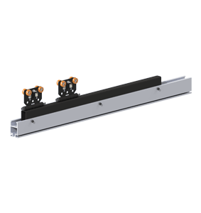
- Travels along the RAD7510 Series Rail.
- Typically used to extend a bridge or runway past the existing bridge.
- Telescoping Rail Includes: RAD7510 Rail, (2) two load trolleys, and a steel backer.
- Attaches to Knight Load Trolleys and End Trucks.
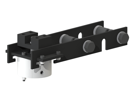
- Pneumatic Brake System.
- Parking brake is also a drag brake when regulator is attached.
- Stroke Size: 0.75 in. [19.1mm].
- Bore Pneumatic Cylinder: 2.00 in. [50.8mm].
- Replaceable Brake Pads.
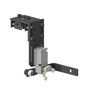
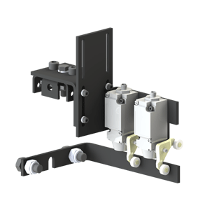
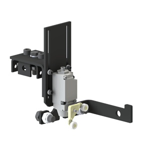
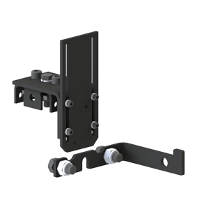
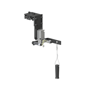
- Attaches to the RAD4110, RAD6110 or RAD7510 Series Rail.
- Single Pole Double-Throw Maintain Switch.
- Allows for pre-defined and pre-determined travel limits to be set.
- Fork Lever Actuator.
- Oil Tight Body.
- Volt Capacity: Up to 600 Volts.
- Easy Bolt-On Installation.
- Allows for pre-defined and pre-determined travel limits to be set.
- Single Pole Double-Throw Maintain Switch.
- Dual Omron Limit Switch (#D4A-3E05N-GM).
- Fork Lever Actuator.
- Oil Tight Body.
- Volt Capacity: Up to 24 VDC.
- Easy Bolt-On Installation.
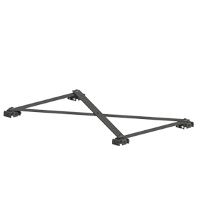
- Stabilizes (2) two bridges to function as one unit.
- Keeps dual bridges from spreading apart.
- Can be configured from the same assembly.
- Attaches to the RAD4110, RAD6110, and RAD7510 Series Rail.
- For bridges over 15 ft. [4.5m], (2) two braces must be used.
- Attaches to Knight Load Trolleys and End Trucks.
- The Rubber Bumper absorbs the impact between two bridges on same runway.
- Limit Switches are sold separately.
- Dual Omron Limit Switch (#D4A-3E05N-GM).
- Allows for pre-defined and pre-determined travel limits to be set.
- Single Pole Double-Throw Maintain Switch.
- Single Omron Limit Switch (#D4A-3E05N-GM).
- Fork Lever Actuator.
- Oil Tight Body.
- Volt Capacity: Up to 24 VDC.
- Easy Bolt-On Installation.
- Limit Switches are sold separately.
- Single Omron Limit Switch (#D4A-3E05N-GM).
- Attaches to the RAD4110, RAD6110 or RAD7510 Series Rail.
- Spring Configuration allows operator to bypass the limit switch.
- Allows for pre-defined and pre-determined travel limits to be set.
- Single Pole Double-Throw Maintain Switch.
- Fork Lever Actuator.
- Oil Tight Body.
- Volt Capacity: Up to 600 Volts.
- Easy Bolt-On Installation.
- Typically used to extend a bridge or runway past the existing bridge.
- Provides an extended reach beyond the working limits of a bridge.
- Telescoping Rail Includes: RAD4110 Rail, (2) Two Load Trolleys, and a Steel Backer.
- Single Pole Double-Throw Maintain Switch.
- Fork Lever Actuator.
- Oil Tight Body.
- Volt Capacity: Up to 600 Volts.
- Allows for pre-defined and pre-determined travel limits to be set.
- Easy Bolt-On Installation.
Hangers
+Filter by Rail Type
- Suspends Knight’s RAD4110, RAD6110, or RAD7510 Series Rail.
- For Direct or Offset Loads.
- Fixed Height Hanger.
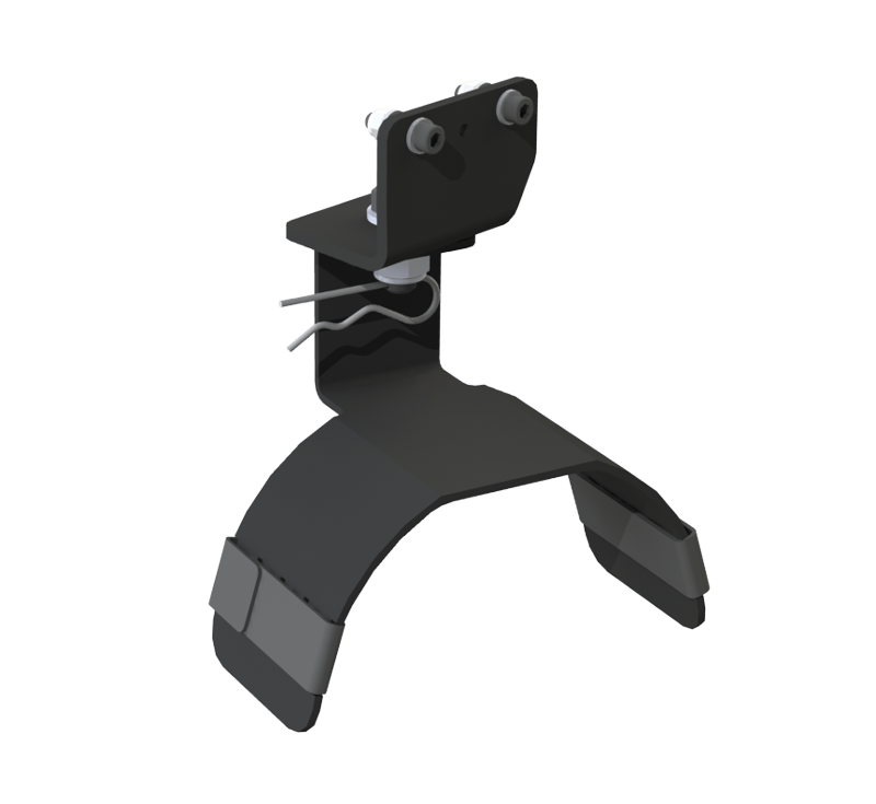
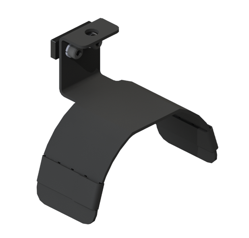
- Hanger is clamped to the top flange of the Knight rail.
- Coated with an environmentally friendly corrosion protection. ** (Autophoretic ACC 900®).
- Attaches to all C-Channel or Angle Iron.
- Optional RWA4133 Safety Cable.
- For Direct Loads.
- Fixed Height Hanger.
- Attaches to all C-Channel or Angle Iron.
- Coated with an environmentally friendly corrosion protection. ** (Autophoretic ACC 900®).
- Optional RWA2133 Safety Cable.
- For Direct Loads.
- Vertical Adjustability: Up to 1.5 in. [38mm]. (Adj. in .25 in. [6.35mm) increments)
- Structural Support Flange Size: 7 in.- 11 in. [178mm – 279mm].
- Max I-Beam Flange thickness: 5/8″ (Thicker flange beams will require modified hanger, available upon request).
- Coated with an environmentally friendly corrosion protection. ** (Autophoretic ACC 900®).
- Optional RWA4133 Safety Cable.
- For Direct or Offset Loads.
- Redundant Structural Support Flange Size: 7 in. – 11 in. [178mm – 279mm].
- Max I-Beam Flange thickness: 7/16″ (Thicker flange beams will require modified hanger, available upon request).
- Fixed Height Hanger.
- Coated with an environmentally friendly corrosion protection. ** (Autophoretic ACC 900®).
- Optional RWA4133 Safety Cable.
- For use with W-Beams Only.
- For Direct Loads Only.
- Rigid Hanger.
- Hanger Grip Range: .25 in. – 0.5625 in. [7mm – 15mm].
- Max I-Beam Flange thickness: 1/2″ (Thicker flange beams will require modified hanger, available upon request).
- Max. Capacity: Up to 3,500 lbs. [1,588kg].
- Coated with an environmentally friendly corrosion protection. ** (Autophoretic ACC 900®).
- Includes RWA4133 Safety Cable.
- Suspends Knight’s RAD4110, RAD6110, or RAD7510 Series Rail.
- For Direct Loads Only.
- Max. Structural Support Flange Size: 2.5 in. [64mm].
- Includes 1 ft. [0.3m] Threaded Rod.
- Coated with an environmentally friendly corrosion protection. ** (Autophoretic ACC 900®).
- Adjustable Height Hanger.
- Maximum C-Channel Flange: 2.5 in. [64mm].
- Optional Threaded Rod: Up to 12 ft. [3.6m] (Each additional 1 ft. [0.6m] of rod adds .905 lbs. [0.41kg] to overall weight.)
- Optional RWA4133 Safety Cable.
- Suspends Knight’s RAD4110, RAD6110, or RAD7510 Series Rail.
- For Direct Loads Only.
- Adjustable Height Hanger.
- Structural Support Flange Size: 2 in. – 7 in. [51mm – 178mm].
- Max I-Beam Flange thickness: 7/16″ (Thicker flange beams will require modified hanger, available upon request).
- Includes: (1) Jam Nuts and (1) Spring Clips.
- Coated with an environmentally friendly corrosion protection. ** (Autophoretic ACC 900®).
- Optional RWA4133 Safety Cable.
- For Direct or Offset Loads Only.
- Vertical Adjustability: Up to 2.0 in. [50.8mm]. (Adj. in .25 in. [6.35mm] increments).
- Structural Support Flange Size: 2 in. – 7 in. [51mm – 178mm].
- Max I-Beam Flange thickness: 5/8″ (Thicker flange beams will require modified hanger, available upon request).
- Coated with an environmentally friendly corrosion protection. ** (Autophoretic ACC 900®).
- Optional RWA4133 Safety Cable.
- Suspends Knight’s RAD4110, RAD6110, or RAD7510 Series Rail.
- For Direct Loads Only.
- Adjustable Height Hanger.
- Structural Support Flange Size: 7 in. – 11 in. [178mm – 279mm].
- Max I-Beam Flange thickness: 7/16″ (Thicker flange beams will require modified hanger, available upon request).
- Includes: (1) Jam Nuts and (1) Spring Clips.
- Coated with an environmentally friendly corrosion protection. ** (Autophoretic ACC 900®).
- Optional RWA4133 Safety Cable.
- Suspends Knight’s RAD4110, RAD6110, or RAD7510 Series Rail.
- For Direct Loads Only.
- Adjustable Height Hanger.
- Structural Support Flange Size: 2 in. – 7 in. [51mm – 178mm].
- Max I-Beam Flange thickness: 7/16″ (Thicker flange beams will require modified hanger, available upon request).
- Includes 1 ft. [0.3m] Threaded Rod.
- Includes: (2) Jam Nuts and (2) Spring Clips.
- Coated with an environmentally friendly corrosion protection. ** (Autophoretic ACC 900®).
- Optional Threaded Rod: Up to 12 ft. [3.6m] (Each additional 1 ft. [0.6m] of rod adds .905 lbs. [0.41kg] to overall weight.)
- Optional RWA4133 Safety Cable.
- Suspends Knight’s RAD4110, RAD6110, or RAD7510 Series Rail.
- For Direct Loads Only.
- Adjustable Height Hanger.
- Structural Support Flange Size: 7 in. – 11 in. [178mm – 279mm].
- Max I-Beam Flange thickness: 7/16″ (Thicker flange beams will require modified hanger, available upon request).
- Includes 1 ft. [0.3m] Threaded Rod.
- Includes: (2) Jam Nuts and (2) Spring Clips.
- Coated with an environmentally friendly corrosion protection. ** (Autophoretic ACC 900®).
- Optional Threaded Rod: Up to 12 ft. [3.6m] (Each additional 1 ft. [0.6m] of rod adds .905 lbs. [0.41kg] to overall weight.)
- Optional RWA4133 Safety Cable.
- For Direct or Offset Loads.
- Redundant Structural Support Flange Sizes: 2 in. – 7 in. [51mm – 178mm].
- Max I-Beam Flange thickness: 7/16″ (Thicker flange beams will require modified hanger, available upon request).
- Fixed Height Hanger.
- Coated with an environmentally friendly corrosion protection. ** (Autophoretic ACC 900®).
- Optional RWA4133 Safety Cable.
- For Direct or Offset Loads.
- Structural Support Flange Size: 2 in. – 7 in. [51mm – 178mm].
- Max I-Beam Flange thickness: 7/16″ (Thicker flange beams will require modified hanger, available upon request).
- Fixed Height Hanger.
- Coated with an environmentally friendly corrosion protection. ** (Autophoretic ACC 900®).
- Optional RWA4133 Safety Cable.
- For Direct or Offset Loads.
- Structural Support Flange Size: 7 in. – 11 in. [178mm – 279mm].
- Max I-Beam Flange thickness: 7/16″ (Thicker flange beams will require modified hanger, available upon request).
- Fixed Height Hanger.
- Coated with an environmentally friendly corrosion protection. ** (Autophoretic ACC 900®).
- Optional RWA4133 Safety Cable.
- Suspends Knight’s RAD4110, RAD6110, or RAD7510 Series Rail.
- For Direct Loads Only.
- Adjustable Height Hanger.
- Attaches to Wide Tubing or Unistrut Size: 2 in. [51mm] to 7 in. [178mm].
- Includes: (1) Jam Nuts and (1) Spring Clips.
- Coated with an environmentally friendly corrosion protection. ** (Autophoretic ACC 900®).
- Optional RWA4133 Safety Cable.
- For Direct or Offset Loads Only.
- Vertical Adjustability: Up to 1.5 in. [38mm]. (Adj. in .25 in. [6.35mm) increments)
- Structural Support Flange Size: 7 in. – 11 in. [178mm – 279mm].
- Max I-Beam Flange thickness: 5/8″ (Thicker flange beams will require modified hanger, available upon request).
- Coated with an environmentally friendly corrosion protection. ** (Autophoretic ACC 900®).
- Optional RWA4133 Safety Cable.
- For Direct or Offset Loads Only.
- Vertical Adjustability: Up to 2.0 in. [50.8mm]. (Adj. in .25 in. [6.35mm] increments).
- Structural Support Flange Size: 7 in. – 11 in. [178mm – 279mm].
- Max I-Beam Flange thickness: 5/8″ (Thicker flange beams will require modified hanger, available upon request).
- Coated with an environmentally friendly corrosion protection. ** (Autophoretic ACC 900®).
- Optional RWA4133 Safety Cable.
- For Direct or Offset Loads Only.
- Vertical Adjustability: Up to 2.0 in. [50.8mm]. (Adj. in .25 in. [6.35mm] increments)
- Structural Support Flange Size: 7 in. – 11 in. [178mm – 279mm].
- Max I-Beam Flange thickness: 5/8″ (Thicker flange beams will require modified hanger, available upon request).
- Coated with an environmentally friendly corrosion protection. ** (Autophoretic ACC 900®).
- Optional RWA4133 Safety Cable.
- For Direct Loads Only.
- Rigid Hanger.
- Structural Support Flange Size: 4 in. – 8 in. [101mm – 203mm].
- Max I-Beam Flange thickness: 1/2″ (Thicker flange beams will require modified hanger, available upon request).
- Hanger Grip Range: .25 in. – 0.5625 in. [7mm – 15mm].
- Max. Capacity: Up to 3,500 lbs. [1588kg].
- Coated with an environmentally friendly corrosion protection. ** (Autophoretic ACC 900®).
- Includes FDA4133 Safety Cable.
- Structural Support Flange Size: 2 in. – 7 in. [51mm – 178mm].
- Used when Hangers Threaded Rod Length is 2 ft. [0.6m] or Greater.
- Max I-Beam Flange thickness: 7/16″ (Thicker flange beams will require modified hanger, available upon request).
- Includes: (6) Jam Nuts.
- Coated with an environmentally friendly corrosion protection. ** (Autophoretic ACC 900®)
- Optional Threaded Rod: Up to 12 ft. [3.6m] (Each additional 1 ft. [0.6m] of rod adds .905 lbs. [0.41kg] to overall weight.)
- Structural Support Flange Size: 7 in. – 11 in. [178mm – 279mm].
- Used when Hangers Threaded Rod Length is 2 ft. [0.6m] or Greater.
- Max I-Beam Flange thickness: 7/16″ (Thicker flange beams will require modified hanger, available upon request).
- Includes: (6) Jam Nuts.
- Coated with an environmentally friendly corrosion protection. ** (Autophoretic ACC 900®)
- Optional Threaded Rod: Up to 12 ft. [3.6m] (Each additional 1 ft. [0.6m] of rod adds .905 lbs. [0.41kg] to overall weight.)
- For use with W-Beams Only.
- For Direct Loads Only.
- Includes NICORWA4133 Safety Cable.
- Rigid Hanger.
- Hanger Grip Range: .25 in. – 0.5625 in. [7mm – 15mm].
- Max I-Beam Flange thickness: 1/2″ (Thicker flange beams will require modified hanger, available upon request).
- Max. Capacity: Up to 3,500 lbs. [1,588kg].
- Coated with an environmentally friendly corrosion protection. ** (Autophoretic ACC 900®).
- Rigid hanger for Direct Loads Only.
- Includes NICORWA4133 Safety Cable kit
- Structural Support Flange Size: 4 in. – 8 in. [101mm – 203mm].
- Max I-Beam Flange thickness: 1/2″ (Thicker flange beams will require modified hanger, available upon request).
- Hanger Grip Range: .25 in. – 0.5625 in. [7mm – 15mm].
- Max. Capacity: Up to 3,500 lbs. [1588kg].
- Coated with an environmentally friendly corrosion protection. ** (Autophoretic ACC 900®).
- For Direct Loads.
- Coated with an environmentally friendly corrosion protection. ** (Autophoretic ACC 900®).
- Adjustable Height Hanger Bracket
- Optional Threaded Rod: Up to 12 ft. [3.6m] (Each additional 1 ft. [0.6m] of rod adds .530 lbs. [0.24kg] to overall weight.)
- Mounts to RAD4110, RAD6110 and RAD7510 Series Rail.
- Suspends Knight TR2000 Series Rail.
- Coated with an environmentally friendly corrosion protection. ** (Autophoretic ACC 900®).
- For Direct Loads.
- Maximum C-Channel Flange: Up to 2.5 in. [64mm] .
- Includes 6 in. [0.15m] Threaded Rod. (Each additional 1 ft. [0.6m] of rod adds .530 lbs. [0.24kg] to overall weight.)
- Coated with an environmentally friendly corrosion protection. **(Autophoretic ACC 900®).
- Adjustable Height Hanger.
- Optional Threaded Rod: Up to 12 ft. [3.6m] • Optional RWA2133 Safety Cable.
- For Direct Loads.
- Structural Support Flange Size: 2 in.- 7 in. [51mm – 178mm].
- Max I-Beam Flange thickness: 7/16″ (Thicker flange beams will require modified hanger, available upon request).
- Adjustable Height Hanger.
- Coated with an environmentally friendly corrosion protection. ** (Autophoretic ACC 900®).
- Optional RWA2133 Safety Cable.
- For Direct or Offset Loads Only.
- Vertical Adjustability: Up to 2 in. [50.8mm]. (Adj. in .25 in. [6.35mm] increments)
- Structural Support Flange Size: 2 in. – 7 in. [51mm – 178mm].
- Max I-Beam Flange thickness: 5/8″ (Thicker flange beams will require modified hanger, available upon request).
- Coated with an environmentally friendly corrosion protection. ** (Autophoretic ACC 900®).
- Optional RWA4133 Safety Cable.
- For Direct Loads.
- Structural Support Flange Size: 7 in.- 11 in. [178mm – 279mm].
- Max I-Beam Flange thickness: 7/16″ (Thicker flange beams will require modified hanger, available upon request).
- Adjustable Hanger Height.
- Coated with an environmentally friendly corrosion protection. ** (Autophoretic ACC 900®).
- Optional RWA2133 Safety Cable.
- For Direct Loads.
- Structural Support Flange Size: 2 in. – 7 in. [51mm – 178mm].
- Max I-Beam Flange thickness: 7/16″ (Thicker flange beams will require modified hanger, available upon request).
- Adjustable Hanger Height.
- Includes 6 in. [152mm] Threaded Rod. (Each additional 6 in. [152mm] of rod adds .530 lbs. [0.24kg] to overall weight.)
- Coated with an environmentally friendly corrosion protection. ** (Autophoretic ACC 900®).
- Optional Threaded Rod: Up to 12 ft. [3.6m]
- Optional RWA2133 Safety Cable.
- For Direct Loads.
- Structural Support Flange Size: 7 in.- 11 in. [178mm – 279mm].
- Max I-Beam Flange thickness: 7/16″ (Thicker flange beams will require modified hanger, available upon request).
- Adjustable Hanger Height.
- Includes 6 in. [152mm] Threaded Rod. (Each additional 6 in. [152mm] of rod adds .530 lbs. [0.24kg] to overall weight.)
- Coated with an environmentally friendly corrosion protection. ** (Autophoretic ACC 900®).
- Optional Threaded Rod: Up to 12 ft. [3.6m].
- Optional RWA2133 Safety Cable.
- For offset loads.
- Structural Support Flange Size: 2 in. – 7 in. [51mm – 178mm].
- Max I-Beam Flange thickness: 7/16″ (Thicker flange beams will require modified hanger, available upon request).
- Fixed Hanger Height.
- Coated with an environmentally friendly corrosion protection. ** (Autophoretic ACC 900®).
- Optional RWA4133 Safety Cable.
- For Direct Loads.
- Structural Support Flange Size: 2 in.- 7 in. [51mm – 178mm].
- Max I-Beam Flange thickness: 7/16″ (Thicker flange beams will require modified hanger, available upon request).
- Fixed Hanger Height.
- Coated with an environmentally friendly corrosion protection. ** (Autophoretic ACC 900®).
- For Direct Loads.
- Structural Support Flange Size: 7 in.- 11 in. [178mm – 279mm].
- Max I-Beam Flange thickness: 7/16″ (Thicker flange beams will require modified hanger, available upon request).
- Fixed Hanger Height.
- Parallel to I-Beam.
- Coated with an environmentally friendly corrosion protection. ** (Autophoretic ACC 900®).
- For offset loads.
- Structural Support Flange Size: 7 in. – 11 in. [178mm – 279mm].
- Max I-Beam Flange thickness: 7/16″ (Thicker flange beams will require modified hanger, available upon request).
- Fixed Hanger Height.
- Coated with an environmentally friendly corrosion protection. ** (Autophoretic ACC 900®).
- Optional RWA4133 Safety Cable.
- For Direct or Offset Loads Only.
- Vertical Adjustability: Up to 2 in. [50.8mm]. (Adj. in .25 in. [6.35mm] increments).
- Structural Support Flange Size: 7 in. – 11 in. [177.8mm – 279.4mm].
- Max I-Beam Flange thickness: 5/8″ (Thicker flange beams will require modified hanger, available upon request).
- Coated with an environmentally friendly corrosion protection. ** (Autophoretic ACC 900®).
- Optional RWA4133 Safety Cable.
- For Direct or Offset Loads Only.
- Vertical Adjustability: Up to 2 in. [50.8mm]. (Adj. in .25 in. [6.35mm] increments)
- Structural Support Flange Size: 7 in. – 11 in. [177.8mm – 279.4mm].
- Max I-Beam Flange thickness: 5/8″ (Thicker flange beams will require modified hanger, available upon request).
- Coated with an environmentally friendly corrosion protection. ** (Autophoretic ACC 900®).
- Optional RWA4133 Safety Cable.
Load Trolleys
+Filter by Rail Type
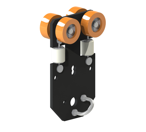
- Recommended for the optimum Balancer Load Trolley.
- Fiberglass filled High Impact Nylon Wheels.
- Side Guide Rollers with integrated bearings.
- Double-shielded wheel bearings keep dirt out, and do not require lubrication.
- Min/ Max Continuous Service Temp at 100% load: -20 degs. F to 248 degs. F.
- Fiberglass filled High Impact Nylon Wheels.
- Side Guide Rollers with integrated bearings.
- Double-Shielded bearings keep dirt out, and do not require lubrication.
- Min/ Max Continuous Service Temp at 100% load: -20 degs. F to 248 degs. F.
- Fiberglass filled High Impact Nylon Wheels.
- Side Guide Rollers with integrated bearings.
- Double-shielded wheel bearings keep dirt out, and do not require lubrication.
- Min/ Max Continuous Service Temp at 100% load: -20 degs. F to 248 degs. F.
- Eye Hook Inside Diameter: 1.00 in. [25.4mm].
- Eye Hook Outer Diameter: 2.13 in. [54.1mm].
- Side Guide Rollers with integrated bearings.
- Fiberglass filled High Impact Nylon Wheels.
- Double-Shielded bearings keep dirt out, and do not require lubrication.
- Min/ Max Continuous Service Temp at 100% load: -20 degs. F to 248 degs. F.
- Fiberglass filled High Impact Nylon Wheels.
- Side Guide Rollers with integrated bearings.
- Double-shielded wheel bearings keep dirt out, and do not require lubrication.
- Min/ Max Continuous Service Temp at 100% load: -20 degs. F to 248 degs. F.
- Fiberglass filled High Impact Nylon Wheels.
- Side Guide Rollers with integrated bearings.
- Double-Shielded bearings keep dirt out, and do not require lubrication.
- Min/ Max Continuous Service Temp at 100% load: -20 degs. F to 248 degs. F.
- Fiberglass filled High Impact Nylon Wheels.
- Side Guide Rollers with integrated bearings.
- Double-Shielded bearings keep dirt out, and do not require lubrication.
- Min/ Max Continuous Service Temp at 100% load: -20 degs. F to 248 degs. F.
- Fiberglass filled High Impact Nylon Wheels.
- Side Guide Rollers with integrated bearings.
- Double-Shielded bearings keep dirt out, and do not require lubrication.
- Min/ Max Continuous Service Temp at 100% load: -20 degs. F to 248 degs. F.
- Fiberglass filled High Impact Nylon Wheels.
- Side Guide Rollers with integrated bearings.
- Double-shielded wheel bearings keep dirt out, and do not require lubrication.
- Min/ Max Continuous Service Temp at 100% load: -20 degs. F to 248 degs. F.
- Travels inside RAD4110 Series Rail.
- Suspends Knight’s ATA2800 or ATA2900 Torque Tubes.
- Fiberglass filled High Impact Nylon Wheels.
- Side Guide Rollers with integrated bearings.
- Double-Shielded bearings keep dirt out, and do not require lubrication.
- Min/ Max Continuous Service Temp at 100% load: -20 degs. F to 248 degs. F.
- Eye Hook Inside Diameter: 1.00 in. [25.4mm].
- Eye Hook Outer Diameter: 2.13 in. [54.1mm].
- Fiberglass filled High Impact Nylon Wheels.
- Side Guide Rollers with integrated bearings.
- Double-Shielded bearings keep dirt out, and do not require lubrication.
- Min/ Max Continuous Service Temp at 100% load: -20 degs. F to 248 degs. F.
- Side Guide Rollers with integrated bearings.
- Fiberglass filled High Impact Nylon Wheels.
- Double-Shielded bearings keep dirt out, and do not require lubrication.
- Min/ Max Continuous Service Temp at 100% load: -20 degs. F to 248 degs. F.
- Side Guide Rollers with integrated bearings.
- Fiberglass filled High Impact Nylon Wheels.
- Double-Shielded bearings keep dirt out, and do not require lubrication.
- Min/ Max Continuous Service Temp at 100% load: -20 degs. F to 248 degs. F.
- Travels inside RAD6110 Series Rail.
- Fiberglass filled High Impact Nylon Wheels.
- Side Guide Rollers with integrated bearings.
- Double-Shielded bearings keep dirt out, and do not require lubrication.
- Min/ Max Continuous Service Temp at 100% load: -20 degs. F to 248 degs. F.
- Fiberglass filled High Impact Nylon Wheels.
- Side Guide Rollers with integrated bearings.
- Double-Shielded bearings keep dirt out, and do not require lubrication.
- Min/ Max Continuous Service Temp at 100% load: -20 degs. F to 248 degs. F.
- Fiberglass filled High Impact Nylon Wheels.
- Side Guide Rollers with integrated bearings.
- Double-shielded wheel bearings keep dirt out, and do not require lubrication.
- Min/ Max Continuous Service Temp at 100% load: -20 degs. F to 248 degs. F.
- Fiberglass filled High Impact Nylon Wheels.
- Eye Hook Inside Diameter: 1.25 in. [31.8mm].
- Eye Hook Outer Diameter: 2.63 in. [66.8mm].
- Side Guide Rollers with integrated bearings.
- Double-Shielded bearings keep dirt out, and do not require lubrication.
- Min/ Max Continuous Service Temp at 100% load: -20 degs. F to 248 degs. F.
- Fiberglass filled High Impact Nylon Wheels.
- Eye Hook Inside Diameter: 1.25 in.[31.8mm].
- Eye Hook Outer Diameter: 2.63 in. [66.8mm].
- Side Guide Rollers with integrated bearings.
- Double-Shielded bearings keep dirt out, and do not require lubrication.
- Min/ Max Continuous Service Temp at 100% load: -20 degs. F to 248 degs. F.
- Fiberglass filled High Impact Nylon Wheels.
- Side Guide Rollers with integrated bearings.
- Double-shielded wheel bearings keep dirt out, and do not require lubrication.
- Min/ Max Continuous Service Temp at 100% load: -20 degs. F to 248 degs. F.
- Fiberglass filled High Impact Nylon Wheels.
- Side Guide Rollers with integrated bearings.
- Double-Shielded bearings keep dirt out, and do not require lubrication.
- Min/ Max Continuous Service Temp at 100% load: -20 degs. F to 248 degs. F.
- Travels inside RAD6110 Series Rail.
- Suspends Knight’s ATA2800 or ATA2900 Torque Tubes.
- Fiberglass filled High Impact Nylon Wheels.
- Side Guide Rollers with integrated bearings.
- Double-Shielded bearings keep dirt out, and do not require lubrication.
- Min/ Max Continuous Service Temp at 100% load: -20 degs. F to 248 degs. F.
- Eye Hook Inside Diameter: 1.25 in.[31.8mm].
- Eye Hook Outer Diameter: 2.63 in. [66.8mm].
- Double-Shielded bearings keep dirt out, and do not require lubrication.
- Fiberglass filled High Impact Nylon Wheels.
- Side Guide Rollers with integrated bearings.
- Min/ Max Continuous Service Temp at 100% load: -20 degs. F to 248 degs. F.
- Travels inside RAD7510 Series Rail.
- Suspends Knight’s ATA2800 or ATA2900 Torque Tubes.
- Fiberglass filled High Impact Nylon Wheels.
- Side Guide Rollers with integrated bearings.
- Double-Shielded bearings keep dirt out, and do not require lubrication.
- Min/ Max Continuous Service Temp at 100% load: -20 degs. F to 248 degs. F.
- Fiberglass filled High Impact Nylon Wheels.
- Side Guide Rollers with integrated bearings.
- Double-Shielded bearings keep dirt out, and do not require lubrication.
- Min/ Max Continuous Service Temp at 100% load: -20 degs. F to 248 degs. F.
- Fiberglass filled High Impact Nylon Wheels.
- Side Guide Rollers with integrated bearings.
- Double-shielded wheel bearings keep dirt out, and do not require lubrication.
- Min/ Max Continuous Service Temp at 100% load: -20 degs. F to 248 degs. F.
- Eye Hook Inside Diameter: 1.25 in.[31.8mm].
- Eye Hook Outer Diameter: 2.63 in. [66.8mm].
- Reduces stack-up heights by: 1.84 in. [47mm].
- Fiberglass filled High Impact Nylon Wheels.
- Side Guide Rollers with integrated bearings.
- Double-Shielded bearings keep dirt out, and do not require lubrication.
- Min/ Max Continuous Service Temp at 100% load: -20 degs. F to 248 degs. F.
- Double-shielded wheel bearings keep dirt out, and do not require lubrication.
- Prevents drag on the load trolley.
- Min/ Max Continuous Service Temp at 100% load: -20 degs. F to 248 degs. F.
- Fiberglass filled High Impact Nylon Wheels.
- Side Guide Rollers with integrated bearings.
- Fiberglass filled High Impact Nylon Wheels.
- Side Guide Rollers with integrated bearings.
- Fiberglass filled High Impact Nylon Wheels.
- Side Guide Rollers with integrated bearings.
- Double-Shielded bearings on the wheels keep dirt out, does not require lubrication.
- Min/ Max Continuous Service Temp at 100% load: -20 degs. F to 248 degs. F.
- Fiberglass filled High Impact Nylon Wheels.
- Side Guide Rollers with integrated bearings.
- Double-Shielded bearings on the wheels keep dirt out, and does not require lubrication.
- Min/ Max Continuous Service Temp at 100% load: -20 degs. F to 248 degs. F.
- Fiberglass filled High Impact Nylon Wheels.
- Side Guide Rollers with integrated bearings.
- Double-Shielded bearings on the wheels keep dirt out, and does not require lubrication.
- Min/ Max Continuous Service Temp at 100% load: -20 degs. F to 248 degs. F.
End Trucks
+Filter by Rail Type
- Suspends Knight RAD4110, RAD6110 and RAD7510 Single Bridges.
- Travels inside RAD7510 Series Rail Runway.
- Dual Trolleys improve bridge travel performance by distributing the overall load across a wider stance.
- Fiberglass filled High Impact Nylon Wheels.
- Side Guide Rollers with integrated bearings.
- Double-Shielded bearings keep dirt out, and do not require lubrication.
- Min/ Max Continuous Service Temp at 100% load: -20 degs. F to 248 degs. F.
- Suspends Knight’s RAD4110 or RAD7510 Single Bridge.
- Travels inside RAD7510 Series Rail Runway.
- Max. Recommended Bridge Length: Up to 15 ft. [4.5m].
- Fiberglass filled High Impact Nylon Wheels.
- Side Guide Rollers with integrated bearings.
- Yoke design allows pivoting in the “X” and “Y” directions for freedom of movement.
- Double-Shielded bearings keep dirt out, and do not require lubrication.
- Min/ Max Continuous Service Temp at 100% load: -20 degs. F to 248 degs. F.
- Suspends Knight RAD4110, RAD6110 and RAD7510 Single Bridges.
- Travels inside RAD7510 Series Rail Runway.
- Max. Recommended Bridge Length: Up to 15 ft. [4.5m].
- Fiberglass filled High Impact Nylon Wheels.
- Side Guide Rollers with integrated bearings.
- Double-Shielded bearings keep dirt out, and do not require lubrication.
- Min/ Max Continuous Service Temp at 100% load: -20 degs. F to 248 degs. F.
- Suspends Knight RAD4110, RAD6110 and RAD7510 Single or Dual Bridges.
- Elevates the bridge to the same height as the runway.
- Intended Bridge Length: Up to 10 ft. [3m].
- Travels inside RAD7510 Series Rail Runway.
- Fiberglass filled High Impact Nylon Wheels.
- Side Guide Rollers with integrated bearings.
- Double-Shielded bearings keep dirt out, and do not require lubrication.
- Min/ Max Continuous Service Temp at 100% load: -20 degs. F to 248 degs. F.
- Suspends Knight RAD4110, RAD6110 and RAD7510 Dual Bridges.
- Travels inside RAD7510 Series Rail Runway.
- End Truck may be adjusted slightly lower or higher on one end of the runway to allow the load trolley to automatically roll back to its home position.
- Incremental Adjustments: 0.38 in. – 0.75 in. [10mm – 19mm].
- Fiberglass filled High Impact Nylon Wheels.
- Side Guide Rollers with integrated bearings.
- Double-Shielded bearings keep dirt out, and do not require lubrication.
- Min/ Max Continuous Service Temp at 100% load: -20 degs. F to 248 degs. F.
- Used with a Knight Trolley.
- Suspends Knight’s RAD4110, RAD6110 RAD7510 Bridges.
- Suspends Knight RAD4110, RAD6110 and RAD7510 Single Bridges.
- Travels Inside RAD4110 Series Rail Runway.
- Max. Recommended Bridge Length: Up to 15 ft. [4.5m].
- Yoke design allows pivoting in the “X” and “Y” directions for freedom of movement.
- Fiberglass filled High Impact Nylon Wheels.
- Side Guide Rollers with integrated bearings.
- Double-Shielded bearings keep dirt out, and do not require lubrication.
- Min/ Max Continuous Service Temp at 100% load: -20 degs. F to 248 degs. F.
- Suspends Knight RAD4110, RAD6110 and RAD7510 Single Bridges.
- Travels Inside RAD4110 Series Rail Runway.
- Max. Recommended Bridge Length: Up to 15 ft. [4.5m].
- Fiberglass filled High Impact Nylon Wheels.
- Side Guide Rollers with integrated bearings.
- Double-Shielded bearings keep dirt out, does not require lubrication and prevents drag on the End Truck.
- Min/ Max Continuous Service Temp at 100% load: -20 degs. F to 248 degs. F.
- Suspends Knight RAD4110, RAD6110 and RAD7510 Single Bridges.
- Travels Inside RAD4110 Series Rail Runway.
- Dual Trolley design improves bridge travel.
- Yoke design allows pivoting in the “X” and “Y” directions for freedom of movement.
- Fiberglass filled High Impact Nylon Wheels.
- Side Guide Rollers with integrated bearings.
- Double-Shielded bearings keep dirt out, does not require lubrication and prevents drag on the end truck.
- Suspends Knight RAD4110 Bridges.
- Travels Inside RAD4110 Series Rail Runway.
- Dual Trolley design improves bridge travel.
- Rigid End truck used when the bridge needs to remain perpendicular to the runways.
- Includes (2) RWA4133 Safety cables.
- Fiberglass filled High Impact Nylon Wheels.
- Side Guide Rollers with integrated bearings.
- Double-Shielded bearings keep dirt out, does not require lubrication and prevents drag on the end truck.
- Suspends Knight RAD4110, RAD6110 and RAD7510 Single Bridges.
- Travels Inside RAD4110 Series Rail Runway.
- Reduces stack-up heights by: 1.32 in. [34mm].
- Max. Recommended Bridge Length: Up to 15 ft. [4.5m].
- Yoke design allows pivoting in the “X” and “Y” directions for freedom of movement.
- Fiberglass filled High Impact Nylon Wheels.
- Side Guide Rollers with integrated bearings.
- Double-Shielded bearings keep dirt out, and do not require lubrication.
- Min/ Max Continuous Service Temp at 100% load: -20 degs. F to 248 degs. F.
- Suspends Knight RAD4110 or RAD7510 Dual Bridge.
- Travels Inside RAD4110 Series Rail Runway.
- Reduces stack-up heights by: 1.32 in. [34mm].
- Fiberglass filled High Impact Nylon Wheels.
- Double-Shielded bearings keep dirt out, does not require lubrication and prevents drag on the end truck.
- Min/ Max Continuous Service Temp at 100% load: -20 degs. F to 248 degs. F.
- Suspends Knight’s RAD4110 or RAD7510 Dual Bridge.
- Travels Inside RAD4110 Series Rail Runway.
- Incremental Adjustments: 0.38 in. – 0.75 in. [10mm – 19mm].
- Fiberglass filled High Impact Nylon Wheels.
- Side Guide Rollers with integrated bearings.
- Double-Shielded bearings keep dirt out, does not require lubrication.
- End truck may be adjusted slightly lower or higher on one end of the runway to allow the load trolley to automatically roll back to its home position.
- Min/ Max Continuous Service Temp at 100% load: -20 degs. F to 248 degs. F.
- Suspends Knight RAD4110, RAD6110 and RAD7510 Single or Dual Bridges.
- Elevates the bridge to the same height as the runway.
- Intended Bridge Length: Up to 10 ft. [3m].
- Travels inside RAD4110 Series Rail Runway.
- Fiberglass filled High Impact Nylon Wheels.
- Side Guide Rollers with integrated bearings.
- Double-Shielded bearings keep dirt out, and do not require lubrication.
- Min/ Max Continuous Service Temp at 100% load: -20 degs. F to 248 degs. F.
- Reduces stack-up heights by: 11.5 in. [292mm].
- Elevates the bridge to the same height as the runway.
- Intended Bridge Length: Up to 10 ft. [3m].
- Suspends Knight’s RAD4110 Single or Dual Bridges.
- Travels Inside RAD4110 Series Rail Runway.
- Fiberglass filled High Impact Nylon Wheels.
- Side Guide Rollers with integrated bearings.
- Double-Shielded bearings keep dirt out, and do not require lubrication.
- Min/ Max Continuous Service Temp at 100% load: -20 degs. F to 248 degs. F.
- Suspends Knight’s RAD4110, RAD6110, or RAD7510 Dual Bridge.
- Travels inside RAD6110 Series Rail Runway.
- Max. Recommended Bridge Length: Up to 15 ft. [4.5m].
- Fiberglass filled High Impact Nylon Wheels.
- Side Guide Rollers with integrated bearings.
- Double-Shielded bearings keep dirt out, and do not require lubrication.
- Min/ Max Continuous Service Temp at 100% load: -20 degs. F to 248 degs. F.
- Suspends Knight’s RAD4110, RAD6110, or RAD7510 Single or Dual Bridge.
- Travels inside RAD6110 Series Rail Runway.
- Dual Trolleys improve bridge travel performance by distributing the overall load across a wider stance.
- Fiberglass filled High Impact Nylon Wheels.
- Side Guide Rollers with integrated bearings.
- Yoke design allows pivoting in the “X” and “Y” directions for freedom of movement.
- Double-Shielded bearings keep dirt out, and do not require lubrication.
- Min/ Max Continuous Service Temp at 100% load: -20 degs. F to 248 degs. F.
- Travels inside RAD6110 Series Rail Runway.
- Fiberglass filled High Impact Nylon Wheels.
- Max. Recommended Bridge Length: Up to 15 ft. [4.5m].
- Side Guide Rollers with integrated bearings.
- Yoke design allows pivoting in the “X” and “Y” directions for freedom of movement.
- Double-Shielded bearings keep dirt out, and do not require lubrication.
- Min/ Max Continuous Service Temp at 100% load: -20 degs. F to 248 degs. F.
- Suspends Knight’s RAD4110, RAD6110, or RAD7510 Dual Bridge.
- Travels inside RAD6110 Series Rail Runway.
- Max. Recommended Bridge Length: Up to 15 ft. [4.5m].
- Fiberglass filled High Impact Nylon Wheels.
- Side Guide Rollers with integrated bearings.
- Double-Shielded bearings keep dirt out, and do not require lubrication.
- Min/ Max Continuous Service Temp at 100% load: -20 degs. F to 248 degs. F.
- Suspends Knight’s RAD4110, RAD6110, or RAD7510 Single or Dual Bridge.
- Travels inside RAD6110 Series Rail Runway.
- Dual Trolleys improve bridge travel performance by distributing the overall load across a wider stance.
- Fiberglass filled High Impact Nylon Wheels.
- Side Guide Rollers with integrated bearings.
- Double-Shielded bearings keep dirt out, and do not require lubrication.
- Min/ Max Continuous Service Temp at 100% load: -20 degs. F to 248 degs. F.
- Travels inside RAD6110 Series Rail Runway.
- Fiberglass filled High Impact Nylon Wheels.
- Max. Recommended Bridge Length: Up to 15 ft. [4.5m].
- Side Guide Rollers with integrated bearings.
- Yoke design allows pivoting in the “X” and “Y” directions for freedom of movement.
- Double-Shielded bearings keep dirt out, and do not require lubrication.
- Min/ Max Continuous Service Temp at 100% load: -20 degs. F to 248 degs. F.
- Travels inside Knight’s RAD6110 Series Center Bridges.
- Rigid End truck used when the bridge needs to remain perpendicular to the runways.
- Used on center bridges in a tri-runway system.
- Low profile reduces stack up heights.
- Includes (2) RWA4133 Safety cables.
- Fiberglass filled High Impact Nylon Wheels.
- Side Guide Rollers with integrated bearings.
- Double-Shielded bearings keep dirt out, and do not require lubrication.
- Min/ Max Continuous Service Temp at 100% load: -20 degs. F to 248 degs. F.
- Travels inside Knight’s RAD6110 Series Center Bridges.
- Rigid End truck used when the bridge needs to remain perpendicular to the runways.
- Used on center bridges in a tri-runway system.
- Includes (2) RWA4133 Safety cables.
- Fiberglass filled High Impact Nylon Wheels.
- Side Guide Rollers with integrated bearings.
- Double-Shielded bearings keep dirt out, and do not require lubrication.
- Min/ Max Continuous Service Temp at 100% load: -20 degs. F to 248 degs. F.
- Reduces stack-up heights by: 11.5 in. [292mm].
- Elevates the bridge to the same height as the runway.
- Intended Bridge Length: Up to 10 ft. [3m].
- Suspends Knight’s RAD6110 Single or Dual Bridges.
- Travels inside RAD6110 Series Rail Runway.
- Fiberglass filled High Impact Nylon Wheels.
- Side Guide Rollers with integrated bearings.
- Double-Shielded bearings keep dirt out, and do not require lubrication.
- Min/ Max Continuous Service Temp at 100% load: -20 degs. F to 248 degs. F.
- Suspends Knight’s RAD6110 Single or Dual Bridge.
- Travels inside RAD6110 Series Rail Runway.
- Intended Bridge Length: 10 ft. [3m].
- Fiberglass filled High Impact Nylon Wheels.
- Side Guide Rollers with integrated bearings.
- Double-Shielded bearings keep dirt out, and do not require lubrication.
- Min/ Max Continuous Service Temp at 100% load: -20 degs. F to 248 degs. F.
- Suspends Knight’s RAD7510 Single or Dual Bridge.
- Travels inside RAD7510 Series Rail Runway.
- Intended Bridge Length: 10 ft. [3m].
- Fiberglass filled High Impact Nylon Wheels.
- Side Guide Rollers with integrated bearings.
- Double-Shielded bearings keep dirt out, and do not require lubrication.
- Min/ Max Continuous Service Temp at 100% load: -20 degs. F to 248 degs. F.
- Please contact a Knight Representative for applications.
- Suspends Knight’s RAD7510 Single Bridge.
- Travels inside RAD7510 Series Rail Runway.
- Welded for added stability.
- (2) Trolley Connector.
- Dual Yoke/ Dual Pivot Design.
- (4) Bolt Connection.
- Fiberglass filled High Impact Nylon Wheels.
- Side Guide Rollers with integrated bearings.
- Max. Recommended Bridge Length: Up to 15 ft. [4.5m].
- Dual Yoke design allows pivoting in the “X” and “Y” directions for freedom of movement.
- Double-Shielded bearings keep dirt out, and do not require lubrication.
- Min/ Max Continuous Service Temp at 100% load: -20 degs. F to 248 degs. F.
- Suspends Knight RAD4110, RAD6110 and RAD7510 Single or Dual Bridges.
- Travels inside RAD7510 Series Rail Runway.
- Fiberglass filled High Impact Nylon Wheels.
- Side Guide Rollers with integrated bearings.
- Double-Shielded bearings keep dirt out, and do not require lubrication.
- Min/ Max Continuous Service Temp at 100% load: -20 degs. F to 248 degs. F.
- Suspends Knight RAD4110, RAD6110 and RAD7510 Single or Dual Bridges.
- Travels inside RAD7510 Series Rail Runway.
- For Low Profile Applications.
- Fiberglass filled High Impact Nylon Wheels.
- Side Guide Rollers with integrated bearings.
- Double-Shielded bearings keep dirt out, and do not require lubrication.
- Min/ Max Continuous Service Temp at 100% load: -20 degs. F to 248 degs. F.
- Suspends Knight RAD4110, RAD6110 and RAD7510 Dual Bridges.
- Travels inside RAD7510 Series Rail Runway.
- For Low Profile Applications
- Fiberglass filled High Impact Nylon Wheels.
- Side Guide Rollers with integrated bearings.
- Double-Shielded bearings keep dirt out, and do not require lubrication.
- Min/ Max Continuous Service Temp at 100% load: -20 degs. F to 248 degs. F.
- Suspends Knight RAD4110, RAD6110 and RAD7510 Single Bridges.
- Travels inside RAD7510 Series Rail Runway.
- Max. Recommended Bridge Length: Up to 15 ft. [4.5m].
- Yoke design allows pivoting in the “X” and “Y” directions for freedom of movement.
- Fiberglass filled High Impact Nylon Wheels.
- Side Guide Rollers with integrated bearings.
- Double-Shielded bearings keep dirt out, and do not require lubrication.
- Min/ Max Continuous Service Temp at 100% load: -20 degs. F to 248 degs. F.
- Suspends Knight RAD4110, RAD6110 and RAD7510 Single or Dual Bridges.
- Travels inside RAD7510 Series Rail Runway.
- Adjustable from 8.59 in. [218.3mm] to 9.34 in. [237.3mm].
- Includes (2) RWA4133 Safety cables.
- Fiberglass filled High Impact Nylon Wheels.
- Side Guide Rollers with integrated bearings.
- Double-Shielded bearings keep dirt out, and do not require lubrication.
- Min/ Max Continuous Service Temp at 100% load: -20 degs. F to 248 degs. F.
- Fiberglass filled High Impact Nylon Wheels.
- Side Guide Rollers with integrated bearings.
- Yoke design allows pivoting in the “X” and “Y” directions for freedom of movement.
- Double-Shielded bearings keep dirt out, and do not require lubrication.
- Min/ Max Continuous Service Temp at 100% load: -20 degs. F to 248 degs. F.
End Caps / Stops
+Filter by Rail Type
- Primarily used as a dust cover.
- Prevents an end truck or load trolley from exiting the rail.
- When used with a MRAA7511 Mid-Rail Stop it forms The MRAS7533 Redundant End Cap Stop.
- Shock Diameter: 0.88 in. [22mm].
- Shock Length: 8.06 in. [205mm].
- Shock Absorbs up to 229 ft. lbs. [311Nm].
- Dampens the impact force of the load trolley striking the end cap.
- Mounts inside of the RAD7510 Series Rail.
- Separates the working area of a bridge or runway and/ or prevents a bridge from over travel.
- Dampens the impact force of the load trolley striking the mid-rail stop.
- Located mid-rail to halt movement of a KET3000 Tractor.
- Shock Diameter: 1.00 in. [25.4mm].
- Shock Length: 8.06 in. [205mm].
- Shock Absorbs up to 141 ft. lbs. [192Nm).
- Attaches inside of the RAD7510 Series Rail.
- Separates the working area of a bridge or runway and/ or prevents a bridge from over travel.
- Can be used in conjunction with the MRAA4804 End Cap to form the MRAS7533 Redundant End Cap Stop.
- Inner MRAA7511 Mid-Rail Stop.
- Prevents an end truck or load trolley from exiting the rail.
- Primarily used as a dust cover.
- Prevents an end truck or load trolley from exiting the rail.
- When used with a “MRAA4455 Mid-Rail Stop”; it forms The “MRAS4454 Redundant End Cap Stop”.
- Separates the working area of a bridge or runway and/ or prevents a bridge from over travel.
- Dampens the impact force of the load trolley striking the mid-rail stop.
- Shock Diameter: 1.00 in. [25.4mm].
- Shock Length: 8.06 in. [205mm].
- Shock Absorbs up to 106 ft. lbs. [144Nm).
- Separates the working area of a bridge or runway and/ or prevents a bridge from over travel.
- Can be used in conjunction with The “MRAA4011 End Cap”; to form The “MRAS4454 Redundant End Cap Stop”.
- Shock Diameter: 0.88 in. [22mm].
- Shock Length: 8.06 in. [205mm].
- Shock Absorbs up to 229 ft. lbs. [311Nm).
- Dampens the impact force of the load trolley striking the end cap.
- Shock Diameter: 1.38 in. [35mm].
- Shock Length: 8.74 in. [222mm].
- Shock Absorbs up to 212 ft. lbs. [288Nm].
- Separates the working area of a bridge or runway and/ or prevents a bridge from over travel.
- Dampens the impact force of the load trolley striking the mid-rail stop.
- Mounts to the inside of the RAD6110 Series Rail.
- Separates the working area of a bridge or runway and/ or prevents a bridge from over travel.
- Dampens the impact force of the load trolley striking the mid-rail stop.
- Shock Diameter: 1.00 in. [25.4mm].
- Shock Length: 8.06 in. [205mm].
- Shock Absorbs up to 229 ft. lbs. [311Nm].
- Primarily used as a dust cover.
- Prevents an end truck or load trolley from exiting the rail.
- When used with a MRAA6111 Mid-Rail Stop it forms the MRAS6133 Redundant End Cap Stop.
- Attaches to the end of the RAD6110 Series Rail.
- Dampens the impact force of the load trolley striking the end cap.
- Shock Diameter: 0.88 in. [22mm].
- Shock Length: 8.06 in. [205mm].
- Shock Absorbs up to 229 ft. lbs. [311Nm).
- Separates the working area of a bridge or runway and/ or prevents a bridge from over travel.
- Can be used in conjunction with the MRAA6104 End Cap to form the MRAS6133 Redundant End Cap Stop.
- Attaches to the end of the RAD4110 series rail.
- Inner MRAA4455 Mid-Rail Stop.
- Prevents an end truck or load trolley from exiting the rail.
- Inner MRAA6111 Mid-Rail Stop.
- Prevents an end truck or load trolley from exiting the rail.
- Attaches inside of the TR2000 Series Rail.
- Separates the working area of a bridge or runway and/ or prevents a bridge from over travel.
- Primarily used as a dust cover.
- Prevents an end truck or load trolley from exiting the rail.
- When used with a MRSA5070 Mid-Rail Stop it forms a redundant stop.
- Inner MRSA5070 Mid-Rail Stop.
- TRN2016 End Cap is used as a dust cover.
- Prevents an end truck or load trolley from exiting the rail.
Safety Cables
+Filter by Rail Type
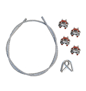
- (4) Crosby® Saddle Clamps
- (2) Cable Thimbles
- (2) Eye Bolts
- (1) Safety Cable made of a carbon steel 7 (strand) x 19 (wires) Galvanized Wire Rope (GWR).
- (2) Copper Oval Sleeves
- (2) Cable Thimbles
- (1) Safety Cable made of a carbon steel 7 (strand) x 19 (wires) Galvanized Wire Rope (GWR).
- Used as Knight’s standard safety cable kit.
- (4) Crosby® Saddle Clamps
- (2) Cable Thimbles
- (1) Safety Cable made of a carbon steel 7 (strand) x 19 (wires) Galvanized Wire Rope (GWR).
Access Gates
+Filter by Rail Type
- Integrated into the RAD7510 Series Rail.
- Allows for maintenance and/ or inspection of a load trolley.
- Easy inspection of system trolleys.
- Does not require additional hangers.
- Attaches to the RAD7510 Series Rail.
- Allows for maintenance and/ or inspection of a load trolley.
- Easy inspection of system trolleys.
- Integrated into the RAD6110 Series Rail.
- Allows for maintenance and/or inspection of a load trolley.
- Easy inspection of system trolleys.
- Does not require additional hangers.
- Attaches to the RAD4110 Series Rail.
- Allows for maintenance and/ or inspection of a load trolley.
- Easy inspection of system trolleys.
- Integrated into the RAD4110 Series Rail.
- Allows for maintenance and/or inspection of a load trolley.
- Easy inspection of system trolleys.
- Does not require additional hangers.
- Integrated into the TR2000 Series Rail.
- Allows for maintenance and/or inspection of a load trolley.
- Easy inspection of system trolleys.
- Does not require additional hangers.
Splice Kits
+Filter by Rail Type
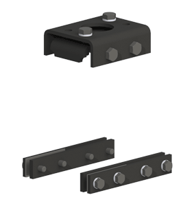
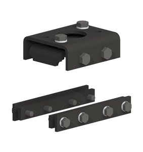
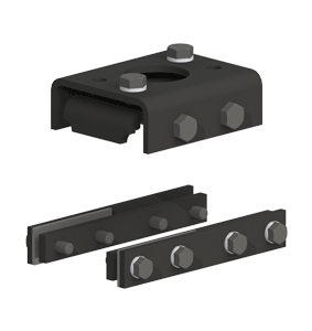
- Splices (2) two sections of the RAD7510 Series Rail.
- Bolt-On Splice Kit.
- Bolt-on kit eliminates need to weld bosses.
- Provides easier access to bolt heads.
- Splices a section of the RAD7500 Curved Series Rail to the RAD7510 Series Rail.
- Bolt-On Splice Kit.
- Bolt-on kit eliminates need to weld bosses.
- Provides easier access to bolt heads.
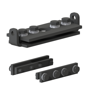
- Splices (2) sections of the RAD4110 Series and RAD6110 Series Rail.
- Bolt-On Splice Kit.
- Bolt-on kit eliminates need to weld bosses.
- Provides easier access to bolt heads.
- Splices a section of the RAD4100 Curved Series Rail to a section of the RAD4110 Series Rail.
- Bolt-On Splice Kit.
- Bolt-on kit eliminates need to weld bosses.
- Provides easier access to bolt heads.
- Splices (2) two sections of TR2000 Series Rail.
- Bolt-On Splice Kit.
- Bolt-on kit eliminates need to weld bosses.
- Provides easier access to bolt heads.
Hose Management
+Filter by Rail Type
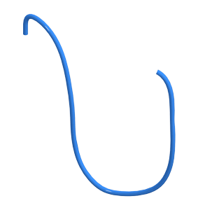
- Designed to eliminate the need for hanging air hoses / festooning.
- Attaches to RAD4110, RAD6110 and RAD7510 Series Rail.
- Can be attached to any bridge and/or runway.
- Max travel: 100 ft. [30m].
- Rail not included.
- Steel Construction.
- Pivoting Joint.
- Supports up to: 2 in. [51mm] Electric Cable or Pneumatic Hose.
- Velcro Straps for Fast and Easy Installation.
- Pivoting Design allows for minimal stack-up lengths.
- Used with RAD7510, 6110 or 4110 Series rail.
- Steel Construction.
- Fixed design.
- Supports up to: 2 in. [51mm] Electric Cable or Pneumatic Hose.
- Velcro Straps for Fast and Easy Installation.
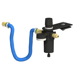
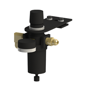
- NPT Filter and Regulator: 1/2 in. [12.7mm].
- Pressure Gauge, Hose and Fittings.
- Controls air flow to the workstation crane.
- Can be used in Knight Aluminum Hose Management kits.
- Supplies Air to Pneumatic Balancers, Tractors, Tooling and End Effectors.
- Festoon Kit includes: – Brackets, Fittings and Messenger Cable for (1) one Runway.
- Hose Fitting Diameters: 1/2 in. [12.7mm].
- Kit does not include the Coiled Hose or Regulator.
- The Hose and Regulator can be purchased separately.
- Supplies Air to Pneumatic Balancers, Tractors, Tooling and End Effectors.
- Festoon Kit includes: – Brackets, Fittings and Messenger Cable for (1) one Bridge.
- Hose Fitting Diameters: 1/2 in. [12.7mm].
- Kit does not include the Coiled Hose or Regulator.
- The Hose and Regulator can be purchased separately.
- Supplies Air to Pneumatic Balancers, Tractors, Tooling and End Effectors.
- Festoon Kit includes: – Brackets, Fittings and Messenger Cable for (1) one Runway.
- Hose Fitting Diameters: 1/2 in. [12.7mm].
- Kit does not include the Straight Hose or Regulator.
- The Hose and Regulator can be purchased separately.
- Supplies Air to Pneumatic Balancers, Tractors, Tooling and End Effectors.
- Festoon Kit includes: – Brackets, Fittings and Messenger Cable for (1) one Bridge.
- Hose Fitting Diameters: 1/2 in. [12.7mm].
- Kit does not include the Straight Hose or Regulator.
- The Hose and Regulator can be purchased separately.
- Supplies Air to Tooling.
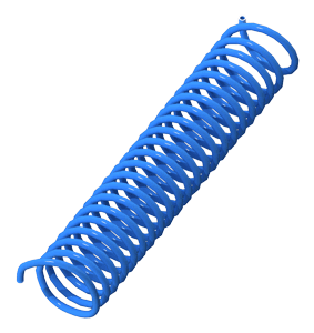
- Material: Nylon Coiled Hose.
- Hose Diameter: 1/2 in. I.D. [12.7mm].
- Hose Capacity: 400 psi [27.5bar].
- 8 ft. [2.4m] of hose is required for every 5 ft. [1.5m] of travel distance.
- Contact a Knight representative to determine the length of hose required for your application.
- Supplies Air to Tooling.
- Material: Nylon Coiled Hose.
- Hose Diameter: 1/2 in. I.D. [12.7mm].
- Hose Capacity: 400 psi [27.5bar].
- Contact a Knight representative to determine the length of hose required for your application.
- NPT Filter and Regulator: 1/2 in. [12.7mm].
- Can be used in Knight Aluminum Hose Management kits.
- Controls air flow to the workstation crane.
Hose Trolleys
+Filter by Rail Type
- Carries festooned hose used in hose management kits.
- Fiberglass filled High Impact Nylon Wheels.
- Side Guide Rollers with integrated bearings.
- Double-Shielded bearings keep dirt out, and do not require lubrication.
- Min/ Max Continuous Service Temp at 100% load: -20 degs. F to 248 degs. F.
- Velcro Straps.
- Fiberglass filled High Impact Nylon Wheels.
- Supports Cable and Festooning.
- Side Guide Rollers with integrated bearings.
- Double-Shielded bearings keep dirt out, and do not require lubrication.
- Min/ Max Continuous Service Temp at 100% load: -20 degs. F to 248 degs. F.
- Travels on tag line on the side of the RAD4100, RAD4110, RAD6110, RAD7500, and RAD7510 Series Rails.
- Zero stack-up lengths.
- Carries festooned hose or cable used in hose management kits.
- Fiberglass filled High Impact Nylon Wheels.
- Double-Shielded bearings keep dirt out, and do not require lubrication.
- Min/ Max Continuous Service Temp at 100% load: -20 degs. F to 248 degs. F.
- Carries festooned hose used in hose management kits.
- Fiberglass filled High Impact Nylon Wheels.
- Side Guide Rollers with integrated bearings.
- Double-Shielded bearings keep dirt out, and do not require lubrication.
- Min/ Max Continuous Service Temp at 100% load: -20 degs. F to 248 degs. F.
- Velcro Straps.
- Supports Cable and Festooning.
- Fiberglass filled High Impact Nylon Wheels.
- Side Guide Rollers with integrated bearings.
- Double-Shielded bearings keep dirt out, and do not require lubrication.
- Min/ Max Continuous Service Temp at 100% load: -20 degs. F to 248 degs. F.
- Carries festooned hose used in hose management kits.
- Fiberglass filled High Impact Nylon Wheels.
- Side Guide Rollers with integrated bearings.
- Double-Shielded bearings keep dirt out, and do not require lubrication.
- Min/ Max Continuous Service Temp at 100% load: -20 degs. F to 248 degs. F.
- Travels inside RAD6110 Series Rail.
- Velcro Straps.
- Supports Cable and Festooning.
- Fiberglass filled High Impact Nylon Wheels.
- Side Guide Rollers with integrated bearings.
- Double-Shielded bearings keep dirt out, and do not require lubrication.
- Min/ Max Continuous Service Temp at 100% load: -20 degs. F to 248 degs. F.
- Fiberglass filled High Impact Nylon Wheels.
- Side Guide Rollers with integrated bearings.
- Double-Shielded bearings keep dirt out, and do not require lubrication.
- Min/ Max Continuous Service Temp at 100% load: -20 degs. F to 248 degs. F.
- Velcro Straps.
- Supports Cable and Festooning.
- Fiberglass filled High Impact Nylon Wheels.
- Side Guide Rollers with integrated bearings.
- Double-Shielded bearings keep dirt out, and do not require lubrication.
- Min/ Max Continuous Service Temp at 100% load: -20 degs. F to 248 degs. F.

