Extension Arm Pneumatic Balancer Series
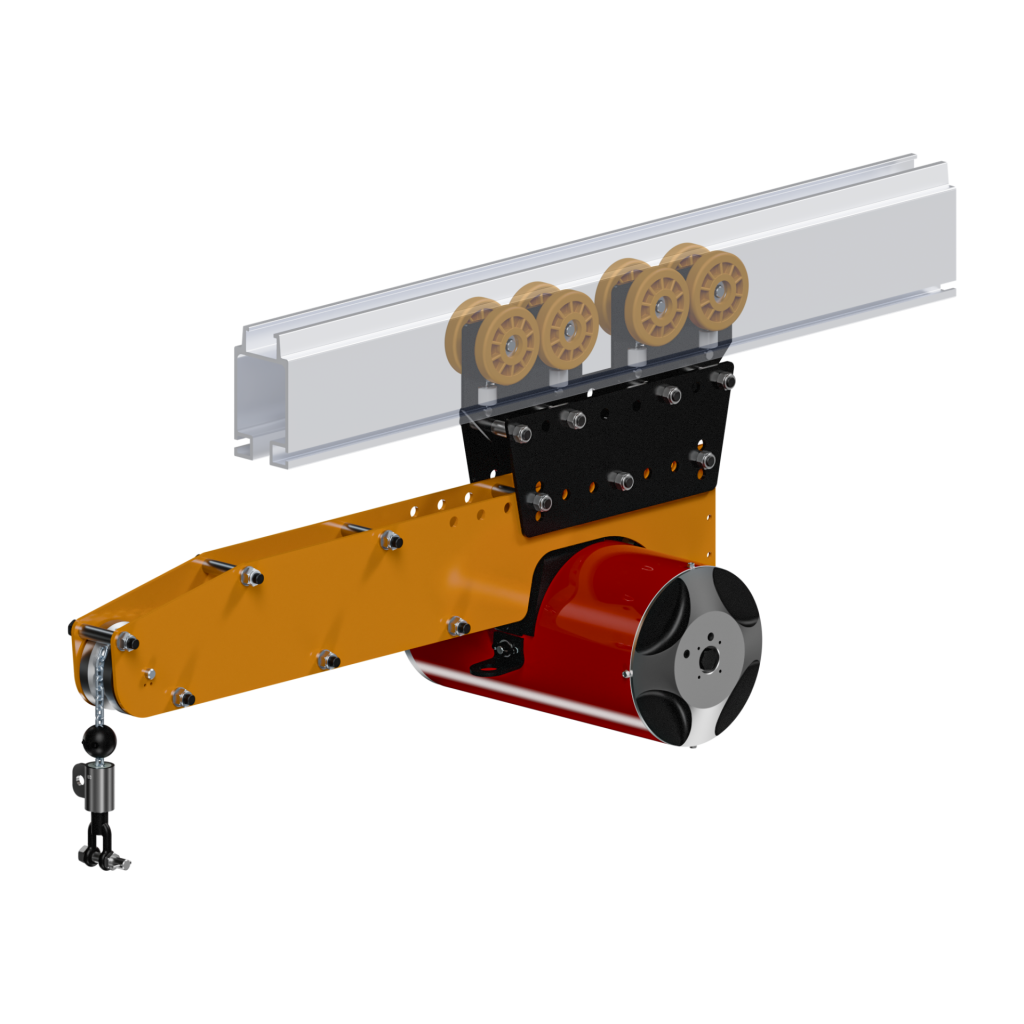
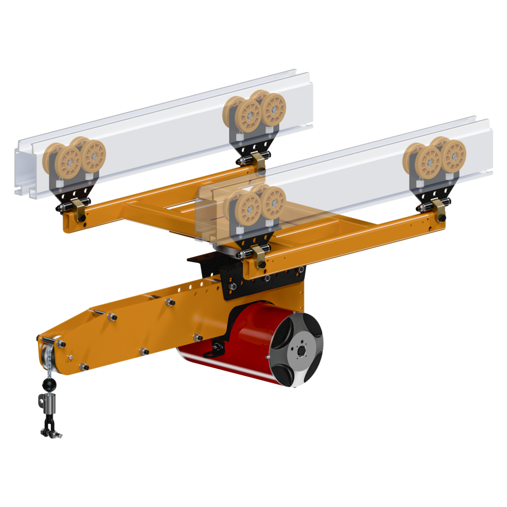
Knight’s Extension Arm Pneumatic Balancer Arm Series enables the operator to extend beyond the working limits of an overhead rail system within a workstation. Our Pneumatic Balancer mounts to the extension arm allowing for a controlled lifting and lowering of loads. The KEAA2000 and KEAA2500 arms travel inside Knight’s RAD4110, RAD6110, or RAD7510 Aluminum Series Rail Systems.
When specifying a pneumatic balancer, it is recommended for working loads to use 80% of the operating capacity for lifting applications. This approach compensates for the normal fluctuations within the plant compressed air supply. Working loads include part weight and handling device weight. Balancers are rated at 100 psi [6.8bar] therefore use the following example to calculate exact operating capability.
Formula for pneumatic balancer sizing: Example: plant air 60 psi, 350 air balancer, 80% load capability (0.60 air supply x 350 lbs. = 210 x .80 = 168 lbs. operating capability).
Contact a Knight representative for more information on our Extension Arm Pneumatic Balancer Arm Series.
To see examples of custom Balancer applications designed by Knight, visit our Gallery.
Resources
Installation Guides
+
Air Balancer Trouble Shooting Guide (Netherlands)

Air Balancer Troubleshooting Guide-2017
Air Balancer Troubleshooting Guide-2021
Air Connection with Balancer Logic Box
Air Connection with Balancer Manifold
External Safety Retract Control Information
Eye Bolt Safety Cable Installation Instructions
Safety Cable Installation Instructions End Trucks, Hangers, Trolleys
General Information
+Features
- Single or Dual Bridge Configuration.
- Travels inside Knight’s RAD4110, RAD6110, or RAD7510 Series Rail.
- CE Compliant.
- Various Control Configurations.
- Angular Adjustment in 10° increments (10° UP / 10° DOWN).
- Horizontal Adjustments: Up to 6.8 in. [172mm]. in 2.3 in. Increments.
- Requires Non-Lubricated Clean/Dry Air.
- Max Balancing Capacity: Up to 700 lbs. [317kg].
- Standard Travel: See Specifications Tab.
Note: Knight recommends the use of high performance, extreme pressure, anti-wear food grade penetrating oil (Lubriplate® 1241 Recommended) that penetrates and lubricates cable. For chain (SAE 50 to 90 EP oil or equivalent machine/gear oil) is Recommended.
Benefits
- Chain Configuration.
- Expands the reach work area of a typical balancer.
- Allows for 360° rotation.
- Controls Sold Separately (Up/ Down or Balance).
Single and Dual Bridge Extension Arm Specifications
+Single Bridge Extension Arm
|
Part
Number |
Capacity
lbs [kg] |
Travel
in. [mm] |
Balancer Length
in. [mm] |
|
KEAA2500-200
|
200 [90]
|
110 [2,794]
|
16.3 [414]
|
|
KEAA2500-350
|
350 [158]
|
67 [1,702]
|
16.3 [414]
|
|
KEAA2500-500
|
500 [226]
|
80 [2,032]
|
21.5 [546]
|
|
KEAA2500-700
|
700 [317]
|
50 [1,270]
|
21.5 [546]
|
Dual Bridge Extension Arm
|
Part
Number |
Capacity
lbs [kg] |
Travel
in. [mm] |
Balancer Length
in. [mm] |
|
KEAA2000-200
|
200 [90]
|
110 [2,794]
|
16.3 [414]
|
|
KEAA2000-350
|
350 [158]
|
67 [1,702]
|
16.3 [414]
|
|
KEAA2000-500
|
500 [226]
|
80 [2,032]
|
21.5 [546]
|
|
KEAA2000-700
|
700 [317]
|
50 [1,270]
|
21.5 [546]
|
Videos
+*Applications Compilation
*Extension Arm – Hood Lift Assist
Air Balancer Manifold & Control Handle Installation
Air Balancer Safety Cable Kit Installation
Air Balancer to Rail Installation
Air Balancer Trolley Installation
Core Casting Lift Assist