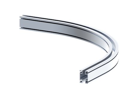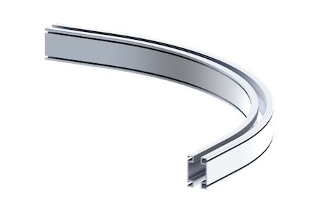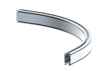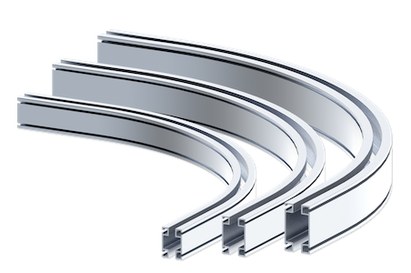
Curved Aluminum Rail Series
Knight’s RAD4112, RAD6112 and RAD7512 Curved Aluminum Rail Series has a curved radius enclosed track that is extruded from a lightweight, high-strength aluminum alloy. This rail design allows loads to travel around corners and stationary objects. The Curved Aluminum Rail Series is the ideal solution for direct loads on single curved sections. This series, combined with nylon trolley wheels, provides the lowest rolling resistance in the industry.
Contact a Knight Global representative for more information on Curved Rail accessories.
Resources
Installation Guides
+
Aluminum Rail General Standards for Materials & Design Process

Aluminum Rail Installation Checklist
Curved Rail Installation Instructions
Curved Rail Secondary Safety Restraint Installation Instructions
Eye Bolt Safety Cable Installation Instructions
Safety Cable Installation Instructions End Trucks, Hangers, Trolleys
General Information
+Features
- Mechanical Properties: ASTM B221 6005-T5 Series Aluminum.
- Standard Radiuses:
- RAD4112
- 3 ft. [0.92m] Min. Radius.
- 8 ft. [2.43m] Max. Radius.
- RAD6112
- 4 ft. [1.21m] Min. Radius.
- 8 ft. [2.43m] Max. Radius.
- RAD7512
- 5 ft. [1.52m] Min. Radius.
- 8 ft. [2.44m] Max. Radius.
- RAD4112
Benefits
- Custom Radiuses Available.
- Load Trolleys and End Trucks are designed for cantilevered and direct load applications.
- All Hangers and End Trucks are designed to prevent binding of bridges and runways.
- Multiple Pre-Assembled Accessories.
- Accessories can be positioned along the rail, no welding required.
Specifications
+Curved Aluminum Rail Series
| Series | Max. Capacity | Product Weight |
|---|---|---|
| RAD4112 | 1,100 lbs. [499kg] | 1.9 lbs/ ft. [.86kg/m] |
| RAD6112 | 1,600 lbs. [725kg] | 2.5 lbs/ ft. [1.13kg/m] |
| RAD7512 | 3,000 lbs. [1,360kg] | 4.0 lbs/ ft. [1.81kg/m] |
RAD4112
+Rail Capacities
| Hanger Span | Deflection Criteria | ||||||
|---|---|---|---|---|---|---|---|
| 1:350 Capacity* | 1:450 Capacity* | 1:550 Capacity* | |||||
| ft | m | lbs | kg | lbs | kg | lbs | kg |
| 5 | 1.52 | 1100 | 499 | 950 | 431 | 700 | 317 |
| 6 | 1.83 | 1100 | 499 | 950 | 431 | 700 | 317 |
| 7 | 2.13 | 1050 | 476 | 875 | 397 | 500 | 227 |
| 8 | 2.45 | 1050 | 476 | 775 | 351 | 500 | 227 |
| 9 | 2.74 | 950 | 431 | 675 | 306 | 425 | 193 |
| 10 | 3.05 | 850 | 385 | 650 | 295 | 425 | 193 |
| 11 | 3.35 | 700 | 317 | 550 | 250 | 350 | 159 |
| 12 | 3.66 | 550 | 250 | 450 | 204 | 300 | 136 |
| 13 | 3.96 | 500 | 226 | 385 | 175 | 250 | 113 |
| 14 | 4.27 | 435 | 197 | 300 | 136 | 250 | 113 |
| 15 | 4.57 | 350 | 159 | 250 | 113 | 200 | 90 |
| 16 | 4.88 | 335 | 152 | 250 | 113 | 200 | 90 |
| 17 | 5.18 | 280 | 127 | 175 | 79 | 150 | 68 |
| 18 | 5.48 | 265 | 120 | 175 | 79 | 150 | 68 |
| 19 | 5.79 | 230 | 104 | 150 | 68 | 125 | 56 |
| 20 | 6.10 | 210 | 95 | 150 | 68 | 125 | 56 |
| 21 | 6.40 | 195 | 88 | 125 | 57 | 125 | 57 |
| 22 | 6.70 | 175 | 79 | 125 | 57 | 100 | 45 |
| 23 | 7.01 | 160 | 73 | 125 | 57 | 100 | 45 |
| 24 | 7.31 | 145 | 66 | 100 | 57 | 75 | 34 |
4.25 (1.9 kg) x 0.35 = 1.48 lbf (0.67 kg) to sustain movement.
RAD6112
+Rail Capacities
| Hanger Span | Deflection Criteria | ||||||
|---|---|---|---|---|---|---|---|
| 1:350 Capacity* | 1:450 Capacity* | 1:550 Capacity* | |||||
| ft | m | lbs | kg | lbs | kg | lbs | kg |
| 5 | 1.52 | 1600 | 725 | 1300 | 590 | 100 | 499 |
| 6 | 1.83 | 1600 | 725 | 1300 | 590 | 100 | 499 |
| 7 | 2.13 | 1500 | 680 | 1175 | 533 | 995 | 451 |
| 8 | 2.45 | 1475 | 699 | 1075 | 488 | 900 | 449 |
| 9 | 2.74 | 1400 | 635 | 1025 | 465 | 870 | 395 |
| 10 | 3.05 | 1325 | 601 | 925 | 453 | 785 | 356 |
| 11 | 3.35 | 1100 | 499 | 875 | 397 | 740 | 336 |
| 12 | 3.66 | 950 | 431 | 750 | 340 | 640 | 290 |
| 13 | 3.96 | 825 | 374 | 650 | 295 | 550 | 250 |
| 14 | 4.27 | 750 | 340 | 575 | 261 | 490 | 222 |
| 15 | 4.57 | 675 | 306 | 515 | 233 | 435 | 197 |
| 16 | 4.88 | 600 | 272 | 470 | 213 | 400 | 181 |
| 17 | 5.18 | 525 | 238 | 405 | 184 | 345 | 157 |
| 18 | 5.48 | 450 | 204 | 350 | 159 | 295 | 134 |
| 19 | 5.79 | 425 | 193 | 325 | 147 | 275 | 125 |
| 20 | 6.10 | 400 | 181 | 300 | 136 | 255 | 116 |
| 21 | 6.40 | 360 | 163 | 275 | 125 | 230 | 104 |
| 22 | 6.70 | 320 | 145 | 250 | 113 | 210 | 95 |
| 23 | 7.01 | 285 | 129 | 210 | 95 | 180 | 82 |
| 24 | 7.31 | 245 | 111 | 185 | 84 | 160 | 73 |
4.25 (1.9 kg) x 0.35 = 1.48 lbf (0.67 kg) to sustain movement.
RAD7512
+Rail Capacities
| Hanger Span | Deflection Criteria | ||||||
|---|---|---|---|---|---|---|---|
| 1:350 Capacity* | 1:450 Capacity* | 1:550 Capacity* | |||||
| ft | m | lbs | kg | lbs | kg | lbs | kg |
| 5 | 1.52 | 3000 | 1360 | 2700 | 1225 | 1700 | 771 |
| 6 | 1.83 | 3000 | 1360 | 2700 | 1225 | 1700 | 771 |
| 7 | 2.13 | 3000 | 1360 | 2700 | 1225 | 1700 | 771 |
| 8 | 2.45 | 3000 | 1360 | 2700 | 1225 | 1700 | 771 |
| 9 | 2.74 | 2700 | 1225 | 2400 | 1088 | 1700 | 771 |
| 10 | 3.05 | 2500 | 1134 | 2000 | 907 | 1700 | 771 |
| 11 | 3.35 | 2500 | 1134 | 1900 | 862 | 1500 | 680 |
| 12 | 3.66 | 2500 | 1134 | 1800 | 816 | 1500 | 680 |
| 13 | 3.96 | 2000 | 907 | 1800 | 816 | 1500 | 680 |
| 14 | 4.27 | 2000 | 907 | 1500 | 680 | 1300 | 590 |
| 15 | 4.57 | 1900 | 861 | 1500 | 680 | 1300 | 590 |
| 16 | 4.88 | 1800 | 816 | 1200 | 544 | 1000 | 454 |
| 17 | 5.18 | 1700 | 771 | 1200 | 544 | 1000 | 454 |
| 18 | 5.48 | 1600 | 726 | 1000 | 453 | 900 | 408 |
| 19 | 5.79 | 1450 | 658 | 1000 | 453 | 900 | 408 |
| 20 | 6.10 | 1300 | 590 | 900 | 408 | 800 | 363 |
| 21 | 6.40 | 1100 | 499 | 900 | 408 | 800 | 363 |
| 22 | 6.70 | 900 | 408 | 800 | 363 | 600 | 272 |
| 23 | 7.01 | 900 | 408 | 700 | 317 | 600 | 272 |
| 24 | 7.31 | 885 | 402 | 700 | 317 | 600 | 272 |
| 25 | 7.62 | 850 | 386 | 700 | 317 | 575 | 261 |
| 26 | 7.92 | 725 | 329 | 700 | 317 | 500 | 250 |
| 27 | 8.23 | 725 | 329 | 675 | 306 | 500 | 227 |
| 28 | 8.53 | 600 | 272 | 550 | 250 | 485 | 220 |
| 29 | 8.83 | 600 | 272 | 550 | 250 | 450 | 204 |
4.25 (1.9 kg) x 0.35 = 1.48 lbf (0.67 kg) to sustain movement.