ERAIL ELECTRIFIED RAIL SYSTEMS*
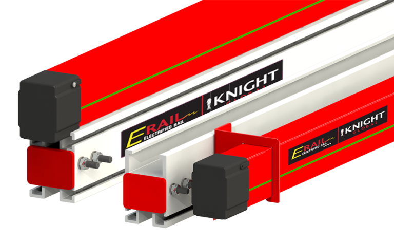
Electrified Rail Systems are a complete power supply suspension system that can be used in combination with a Knight Servo System, VFD tractors, power tools, and other electrical devices.
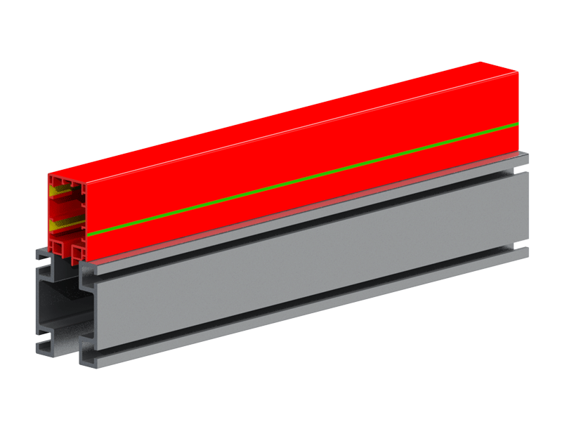
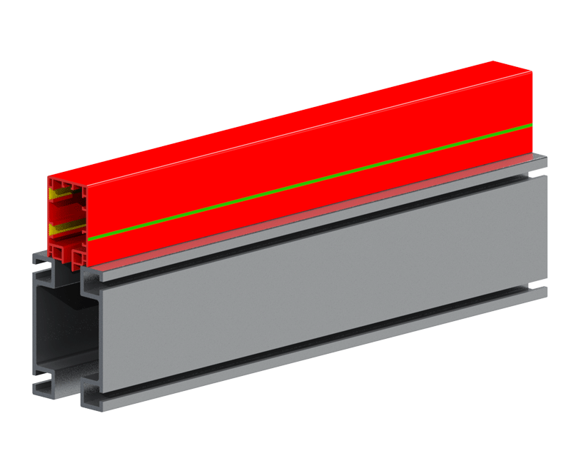
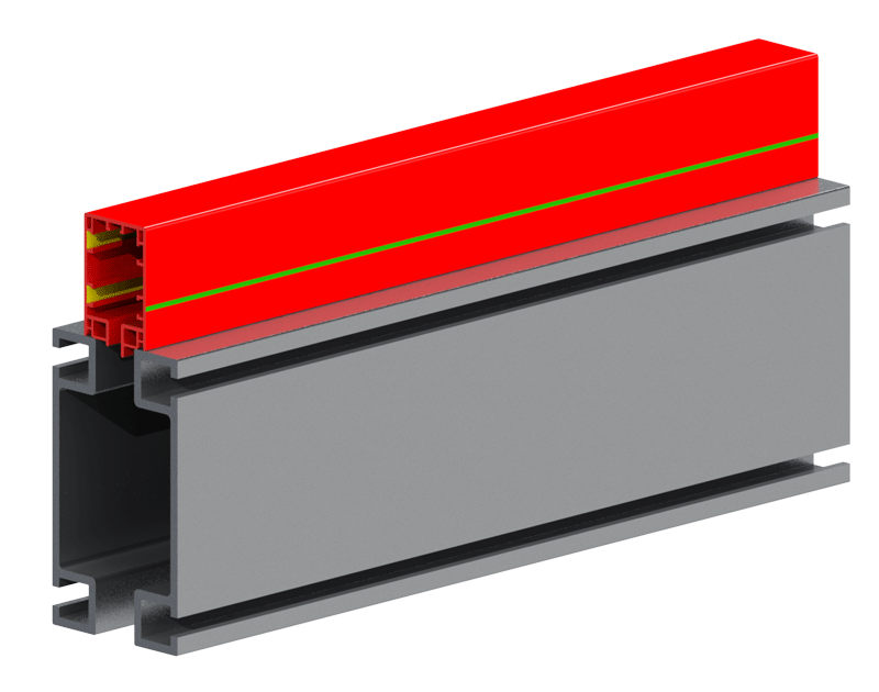
The ERAD Series is a fully enclosed electrical system that eliminates the stack-up of runway festooning. The power travels through a conductor power rail (ERail), mounted on top of Knight’s ERAD4000, ERAD6000, or ERAD7000 ergonomically friendly aluminum rail. The standard ERail is equipped with (4) four poles, nominal current 60 amp, 240/480V which can run multiple systems on (1) one rail assembly.
The Electrified Rail is incredibly diverse in that it can also be mounted to the side of the aluminum rail. The benefits to this configuration include shorter stack-up heights and the use of Knight’s standard rail rather than the custom rail used with the top-mounted style. The side-mounted style can also be retrofitted onto an existing Knight system to eliminate the need for electrical festooning.
*Top-mounted style is Patent Pending

General Information
+Features
- Patent Pending
- Fully Enclosed Electrical System
- ERail Electrical Capacity:
Up to 60 amps / 690 volts - Horizontal curved sections available.
- Max Weight Capacity:
Up to 3,000 lbs [1,360 kg] - Compliant with International Standards.
- Added safety against shock.
- Knight’s unique hanger design allows for adjustments while leveling the system.
Benefits
- Optional mounting configuration: side mounted.
- Eliminates stack-up of festooning trolleys and hanging electrical cables.
- Simplifies installation by including electrical rail within suspension.
- Eliminates need for tow bars.
- Stacked compact design eliminates need from installing load rail and power rail separately.
- Twice the power of the competition.
System Components
+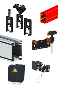 ERail
ERail
Available in 4 poles with a nominal current of 60 A.
ERail Conductor Trolley
Travels inside of the ERail and is combined with the Knight load trolley. Copper graphite shoes are used for energy and control voltages over 35 V.
ERAD4000/ERAD6000/ERAD7000
Combined with Knight’s load trolleys, provides the most ergonomically friendly rail system. Rail comes in lengths up to 25ft [9.1m] without a splice. Capacities up to 3,000 lbs. [1,360 kg].
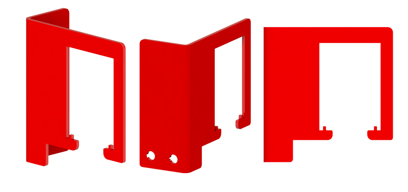
Suspension Points
Knight adjustable hangers and End Trucks support both the Load Rail and ERail. Hangers have the ability to mount to I-Beams, C-Channels, Angle Iron, and many others.
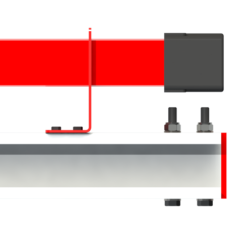
ERail End Caps and Stops
Attaches to the end of the ERail Series Rail. The Redundant End Cap is primarily used to prevent load and ERail trolleys from exiting the rail.
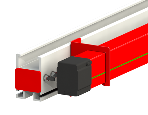
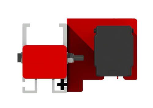
Power Supply End Feed
Power supply feed for ERail. Comes standard with 4 poles.
ERAD4000 Capacity Chart
+ERAD4000 Capacities
| Hanger Span | Deflection Criteria | ||||||
|---|---|---|---|---|---|---|---|
| 1:350 Capacity* | 1:450 Capacity* | 1:550 Capacity* | |||||
| ft | m | lbs | kg | lbs | kg | lbs | kg |
| 5 | 1.52 | 1140 | 517 | 1140 | 517 | 1140 | 517 |
| 6 | 1.83 | 945 | 429 | 945 | 429 | 945 | 429 |
| 7 | 2.13 | 810 | 367 | 810 | 367 | 790 | 358 |
| 8 | 2.45 | 705 | 320 | 705 | 320 | 600 | 272 |
| 9 | 2.74 | 625 | 283 | 575 | 261 | 470 | 213 |
| 10 | 3.05 | 560 | 254 | 460 | 209 | 375 | 170 |
| 11 | 3.35 | 490 | 222 | 375 | 170 | 300 | 136 |
| 12 | 3.66 | 405 | 184 | 310 | 141 | 245 | 111 |
| 13 | 3.96 | 340 | 154 | 255 | 116 | 205 | 93 |
| 14 | 4.27 | 285 | 129 | 215 | 98 | 170 | 77 |
| 15 | 4.57 | 240 | 109 | 180 | 82 | 140 | 64 |
| 16 | 4.88 | 205 | 93 | 150 | 68 | 120 | 54 |
| 17 | 5.18 | 175 | 79 | 130 | 59 | 100 | 45 |
| 18 | 5.49 | 150 | 68 | 110 | 50 | 80 | 36 |
| 19 | 5.79 | 130 | 59 | 90 | 41 | 65 | 29 |
| 20 | 6.10 | 110 | 50 | 75 | 34 | 55 | 25 |
| 21 | 6.40 | 90 | 41 | 60 | 27 | 40 | 18 |
| 22 | 6.71 | 80 | 36 | 50 | 23 | 30 | 14 |
| 23 | 7.01 | 65 | 29 | 40 | 18 | 20 | 9 |
| 24 | 7.32 | 50 | 23 | 30 | 14 | 15 | 7 |
*Due to Ergonomic considerations, each rail span distance is tested to determine the maximum single point load required to achieve a predetermined deflection based on a ratio of 1:350 (1” of deflection for each 350” of length), 1:450 (1” of deflection in 450” of length) or 1:550 (1” of deflection for each 550” of length).
For purposes of estimating approximate ergonomic force requirements, the following formula may be used:
0.009 x total mass = maximum effort (in lbf) required to overcome inertia. Effort required to sustain movement is generally 0.35 x effort to overcome inertia e.g.,
250 lbs. (1.03 kg) mass x 0.009 = 2.25 lbf (0.9 kg) to overcome inertia
2.25 (0.9 kg) x 0.35 = .79 lbf (0.36 kg) to sustain movement
ERAD6000 Capacity Chart
+ERAD6000 Capacities
| Hanger Span | Deflection Criteria | ||||||
|---|---|---|---|---|---|---|---|
| 1:350 Capacity* | 1:450 Capacity* | 1:550 Capacity* | |||||
| ft | m | lbs | kg | lbs | kg | lbs | kg |
| 5 | 1.52 | 2030 | 921 | 2030 | 921 | 2030 | 921 |
| 6 | 1.83 | 1690 | 767 | 1690 | 767 | 1690 | 767 |
| 7 | 2.13 | 1445 | 655 | 1445 | 655 | 1445 | 655 |
| 8 | 2.45 | 1260 | 572 | 1260 | 572 | 1260 | 572 |
| 9 | 2.74 | 1115 | 506 | 1115 | 506 | 1115 | 506 |
| 10 | 3.05 | 1000 | 454 | 1000 | 454 | 895 | 406 |
| 11 | 3.35 | 905 | 411 | 900 | 408 | 730 | 331 |
| 12 | 3.66 | 825 | 374 | 750 | 340 | 605 | 274 |
| 13 | 3.96 | 760 | 345 | 630 | 286 | 510 | 231 |
| 14 | 4.27 | 700 | 318 | 535 | 243 | 430 | 195 |
| 15 | 4.57 | 600 | 272 | 455 | 206 | 365 | 166 |
| 16 | 4.88 | 520 | 236 | 395 | 134 | 310 | 141 |
| 17 | 5.18 | 450 | 204 | 340 | 154 | 270 | 122 |
| 18 | 5.49 | 395 | 179 | 295 | 134 | 230 | 104 |
| 19 | 5.79 | 345 | 156 | 255 | 116 | 195 | 88 |
| 20 | 6.10 | 300 | 136 | 220 | 100 | 170 | 77 |
| 21 | 6.40 | 265 | 120 | 190 | 86 | 145 | 66 |
| 22 | 6.71 | 230 | 104 | 165 | 75 | 125 | 57 |
| 23 | 7.01 | 205 | 93 | 140 | 64 | 105 | 48 |
| 24 | 7.32 | 180 | 82 | 120 | 54 | 85 | 39 |
*Due to Ergonomic considerations, each rail span distance is tested to determine the maximum single point load required to achieve a predetermined deflection based on a ratio of 1:350 (1” of deflection for each 350” of length), 1:450 (1” of deflection in 450” of length) or 1:550 (1” of deflection for each 550” of length).
For purposes of estimating approximate ergonomic force requirements, the following formula may be used:
0.009 x total mass = maximum effort (in lbf) required to overcome inertia. Effort required to sustain movement is generally 0.35 x effort to overcome inertia e.g.,
250 lbs. (1.03 kg) mass x 0.009 = 2.25 lbf (0.9 kg) to overcome inertia
2.25 (0.9 kg) x 0.35 = .79 lbf (0.36 kg) to sustain movement
ERAD7000 Capacity Chart
+ERAD7000 Capacities
| Hanger Span | Deflection Criteria | ||||||
|---|---|---|---|---|---|---|---|
| 1:350 Capacity* | 1:450 Capacity* | 1:550 Capacity* | |||||
| ft | m | lbs | kg | lbs | kg | lbs | kg |
| 5 | 1.52 | 3000 | 1360 | 3000 | 1360 | 3000 | 1360 |
| 6 | 1.83 | 3000 | 1360 | 3000 | 1360 | 3000 | 1360 |
| 7 | 2.13 | 3000 | 1360 | 3000 | 1360 | 3000 | 1360 |
| 8 | 2.45 | 2940 | 1334 | 2940 | 1334 | 2940 | 1334 |
| 9 | 2.74 | 2610 | 1184 | 2610 | 1184 | 2610 | 1184 |
| 10 | 3.05 | 2345 | 1064 | 2345 | 1064 | 2345 | 1064 |
| 11 | 3.35 | 2130 | 966 | 2130 | 966 | 2130 | 966 |
| 12 | 3.66 | 1945 | 882 | 1945 | 882 | 1945 | 882 |
| 13 | 3.96 | 1795 | 814 | 1795 | 814 | 1720 | 780 |
| 14 | 4.27 | 1660 | 753 | 1660 | 753 | 1475 | 669 |
| 15 | 4.57 | 1545 | 701 | 1545 | 701 | 1275 | 578 |
| 16 | 4.88 | 1445 | 655 | 1370 | 621 | 1110 | 503 |
| 17 | 5.18 | 1355 | 615 | 1205 | 547 | 975 | 442 |
| 18 | 5.49 | 1280 | 581 | 1065 | 483 | 860 | 390 |
| 19 | 5.79 | 1205 | 547 | 950 | 431 | 765 | 347 |
| 20 | 6.10 | 1105 | 501 | 845 | 383 | 680 | 308 |
| 21 | 6.40 | 995 | 451 | 760 | 345 | 610 | 277 |
| 22 | 6.71 | 895 | 406 | 685 | 311 | 545 | 247 |
| 23 | 7.01 | 810 | 367 | 615 | 279 | 490 | 222 |
| 24 | 7.32 | 735 | 333 | 555 | 252 | 440 | 200 |
*Due to Ergonomic considerations, each rail span distance is tested to determine the maximum single point load required to achieve a predetermined deflection based on a ratio of 1:350 (1” of deflection for each 350” of length), 1:450 (1” of deflection in 450” of length) or 1:550 (1” of deflection for each 550” of length).
For purposes of estimating approximate ergonomic force requirements, the following formula may be used:
0.009 x total mass = maximum effort (in lbf) required to overcome inertia. Effort required to sustain movement is generally 0.35 x effort to overcome inertia e.g.,
250 lbs. (1.03 kg) mass x 0.009 = 2.25 lbf (0.9 kg) to overcome inertia
2.25 (0.9 kg) x 0.35 = .79 lbf (0.36 kg) to sustain movement
Videos
+*ERail Electrified Rail Systems
Accessories
General
+Hangers
+Load Trolleys
+End Trucks
+End Caps / Stops
+Splice Kits
+